Tissue Matrix System

Active Publication Date: 2011-10-20
ISTO TECH II LLC
View PDF3 Cites 26 Cited by
  • Summary
  • Abstract
  • Description
  • Claims
  • Application Information

AI Technical Summary

Benefits of technology

[0026]In various aspects of the present teachings, a matrix comprising a polyester entangled with a polysaccharide can be comprised by a solid such as a plug, a granule, or a membrane. Furthermore, in some embodiments, a matrix can be in an injectable form, e.g., as a slurry, a paste or a viscous fluid. The a matrix of these embodiments can have a viscosity ranging from about from about 200,000 centipoise to about 3×101 centipoise at 20° C., from about 106 centipoise to about 109 centipoise at 20° C., or from about 1.5×10⁶ centipoise to about 108 centipoise at 20° C. In addition, in some configurations, a matrix can be comprised by a paste. In some configurations, a matrix ca

Problems solved by technology

Although some bone substitutes are available, many consist of materials that have poor physical

Method used


Image

  • Tissue Matrix System
  • Tissue Matrix System
  • Tissue Matrix System

Examples


example 2

[0056]This example illustrates implant site preparation and post-implantation of a matrix in an animal model experimental system.

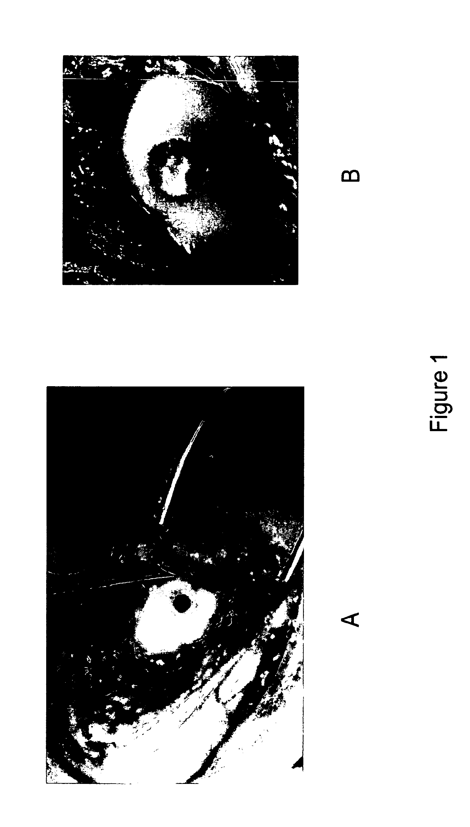
[0057]In this example, as shown in FIG. 1, a circular defect was created in the weight-bearing region of the medial femoral condyle of a skeletally mature sheep using a 5.5 mm diameter OATS-type punch to a depth of 6 mm in an animal model of an osteochondral defect (FIG. 1a). The defect was then flushed with sterile saline prior to insertion of a test matrix. An entangled polyester-polysaccharide matrix comprising PLA-PGA copolymer and hyaluronic acid as described in Example 1 was then press-fit into the defect using a blunt instrument. FIG. 1b shows the implant site post-implantation.

example 3

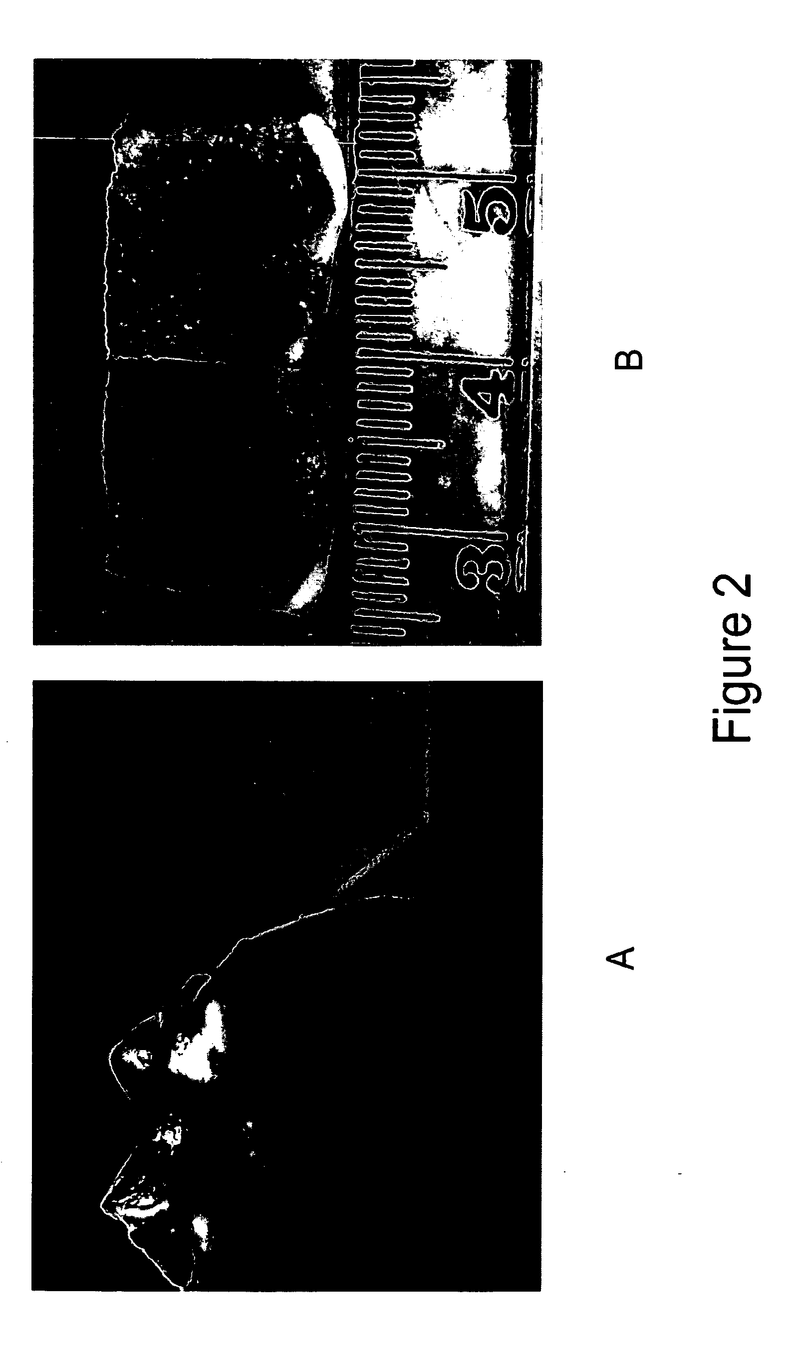
[0058]This example illustrates healing three months after the intervention illustrated in Example 2. FIG. 2 shows an example of gross outcome at 3 months. Gross image of the femoral condyle (FIG. 2a) and cross section of the tissue at the defect site (FIG. 2b) reveals new tissue formation fully integrated with the native cartilage and no evidence of inflammation at the site. FIG. 2b is a cross section of the implant site after decalcification showing extensive ingrowths and replacement of the implant with cartilage and bone. Animals having similar defects but not receiving an entangled polyester-polysaccharide matrix do not show the same extent of ingrowth of cartilage and bone.

example 4

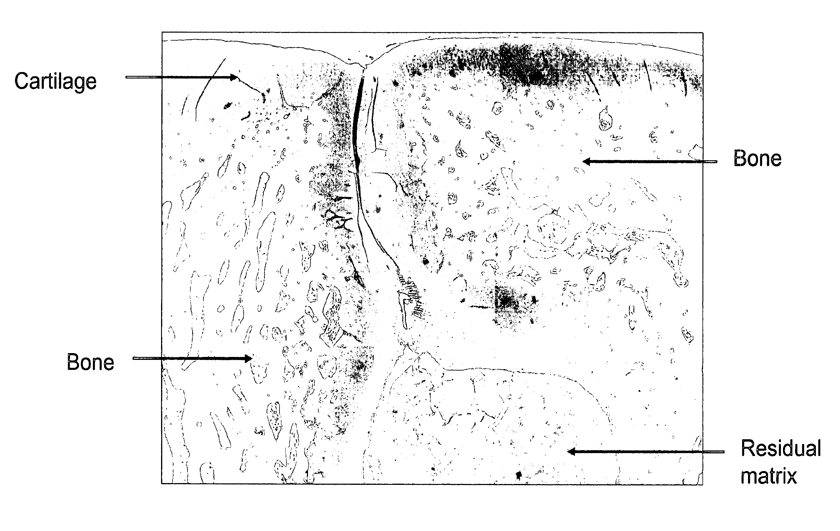
[0059]This example illustrates histological analysis of the 3-month post-intervention tissue presented in Example 3, and demonstrates hyaline cartilage repair with active osteogenesis at the core of the implant. In this example, as shown in FIG. 3, the tissue was stained with Safranin-O to visualize the cartilage proteoglycans found in the native and newly formed cartilage. FIG. 3 indicates that new cartilage and bone at the site of intervention become recognizable histologically upon examination 3 months following the procedure. FIG. 3 further indicates that greater than 50% of the composite implant was degraded / resorbed by 3 months post-intervention and was replace by newly formed bone and cartilage. Dashed line shows the marking of the surgical defect.

Example 5

[0060]This example illustrates formation of cartilage and bone three months post-intervention. As shown in FIG. 4, light microscopy of an area close to the implant site reveals active formation of cartilage from undifferent...


PUM

PropertyMeasurementUnit
Weight ratioaaaaaaaaaa
Viscosityaaaaaaaaaa
Therapeuticaaaaaaaaaa

Abstract

The present application discloses matrix compositions to support the repair of tissue defects such as an injury to tendon tissue, ligament tissue, vascular tissue, dermal tissue, or muscle tissue. A matrix described herein comprises a polyester polymer entangled with a polysaccharide polymer. Also disclosed are methods of preparing a matrix, and methods of using a matrix in the repair of tissue. In certain configurations, a matrix can comprise a polyester cross-linked with a polysaccharide, which can be an oxidized polysaccharide. In some configurations, a matrix can further comprise one or more additional components, such as a growth factor or an anti-infective agent. In some configurations, a matrix can be a viscous fluid or a paste, while in other configurations a matrix can be comprised by a solid such as a plug, a granule or a membrane.

Description

CROSS-REFERENCE TO RELATED APPLICATIONS[0001]This application is a continuation application of copending U.S. Pat. Appl. Ser. No. 11 / 448,701, filed Jun. 7, 2006, which is a continuation in part of copending U.S. Pat. Appl. Ser. No. 11 / 179,425, filed Jul. 11, 2005, which claims priority from Provisional patent application Ser. No. 60 / 587,088, filed Jul. 12, 2004, the disclosures of which are herein incorporated by reference in their entireties.BACKGROUND[0002]There is a clinical demand for biocompatible matrices that offer tissue growth-conductive and or growth-inductive properties resembling those of autologous tissue and that can be produced in unlimited supply, for tissues such as bone, cartilage, connective tissue or soft tissue. Although some bone substitutes are available, many consist of materials that have poor physical handling and resorption characteristics that complicate their use and radiographic evaluation.[0003]U.S. Pat. No. 6,673,285 to Ma, issued Jan. 6, 2004 disclos...

Claims


Application Information

Patent Timeline
IPC IPC(8): A61K47/36A61K38/18A61K38/48C12N5/071A61K38/19A61K38/39A61P19/00A61P19/04A61K47/46A61K38/20
CPCA61K31/727A61K31/728A61K31/737A61L27/26A61K38/00C08L67/04C08L5/00A61P19/00A61P19/04A61L27/50A61L2400/06
Inventor SEYEDIN, MITCHELL S.GAGE, GARY
Owner ISTO TECH II LLC
Why Eureka
Try Eureka