
Method for manufacturing electrophoretic display apparatus

a technology of electrophoretic display and electrophoretic gel, which is applied in the direction of liquid surface applicators, instruments, coatings, etc., can solve the problems of limiting the choice of solvent, difficult to synthesize fluorine-containing solvents, and high cost of materials, so as to reduce the cost of materials, high versatility and inexpensive

Active Publication Date: 2011-10-20
E INK CORPORATION
View PDF3 Cites 5 Cited by
  • Summary
  • Abstract
  • Description
  • Claims
  • Application Information

AI Technical Summary

Benefits of technology

[0012]An advantage of some aspects of the invention is that they make possible to manufacture an electrophoretic display apparatus free from the blending of the dispersion liquid and the sealing coating at reduced material cost.
[0013]To provide this advantage, the method for manufacturing an electrophoretic display apparatus according to an aspect of the invention includes the following: loading cells spatially defined by partitions with a dispersion liquid containing electrophoretically mobile particles and a dispersion medium for dispersing the electrophoretically mobile particles, and covering the exposed surface of the dispersion liquid loaded in the cells with a sealing coating to seal the dispersion liquid in the cells. The dispersion medium is a lipophilic hydrocarbon solvent, and the sealing coating is made from a material containing a water-soluble compound. To be able to form a coating easily, the water-soluble compound is preferably a water-soluble polymer.
[0014]A method designed as above allows using a hydrocarbon solvent, which is available at affordable prices, as the dispersion medium and thereby reduces the cost of the materials for the dispersion liquid. As a result, the manufacturing cost of the electrophoretic display apparatus is reduced. Furthermore, the dispersion liquid and the sealing coating will be prevented from being mixed (i.e., blended), and thus the dispersion liquid can be kept tightly sealed in the cells.

Problems solved by technology

However, fluorine-containing solvents are difficult to synthesize, and materials for them are expensive.
Worse yet, there are only a few kinds of fluorine-containing solvents available, limiting the choice of solvent.
However, the use of a hydrocarbon solvent may cause the blending of the dispersion liquid and the sealing coating.
For example, using a lipophilic sealing coating concomitantly with a lipophilic hydrocarbon solvent may result in the sealing coating at least in part dissolved in the dispersion liquid and the sealing coating and the dispersion liquid being blended, leading to incomplete sealing of the dispersion liquid.
The technology disclosed in JP-T-2006-517038 does not necessitate making the sealing coating from a material substantially immiscible with the dispersion liquid because with this technology the sealing coating and the dispersion liquid will never be blended even if the dispersion liquid loaded in the cells is contaminated by or coated with the sealing coating whether the sealing coating is hydrophilic or lipophilic.
On the other hand, using a hydrocarbon solvent as the dispersion medium may cause the sealing coating and the dispersion liquid to be blended and thus poses the problem of the need for making the sealing coating from a material substantially immiscible with the dispersion liquid.

Method used


Image

  • Method for manufacturing electrophoretic display apparatus
  • Method for manufacturing electrophoretic display apparatus
  • Method for manufacturing electrophoretic display apparatus

Examples


first embodiment

I. First Embodiment

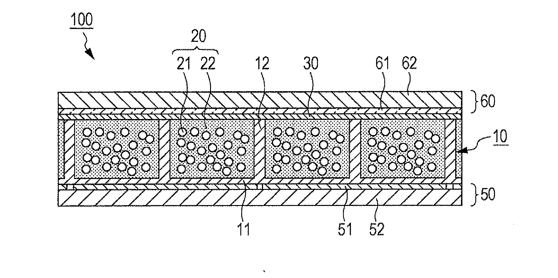
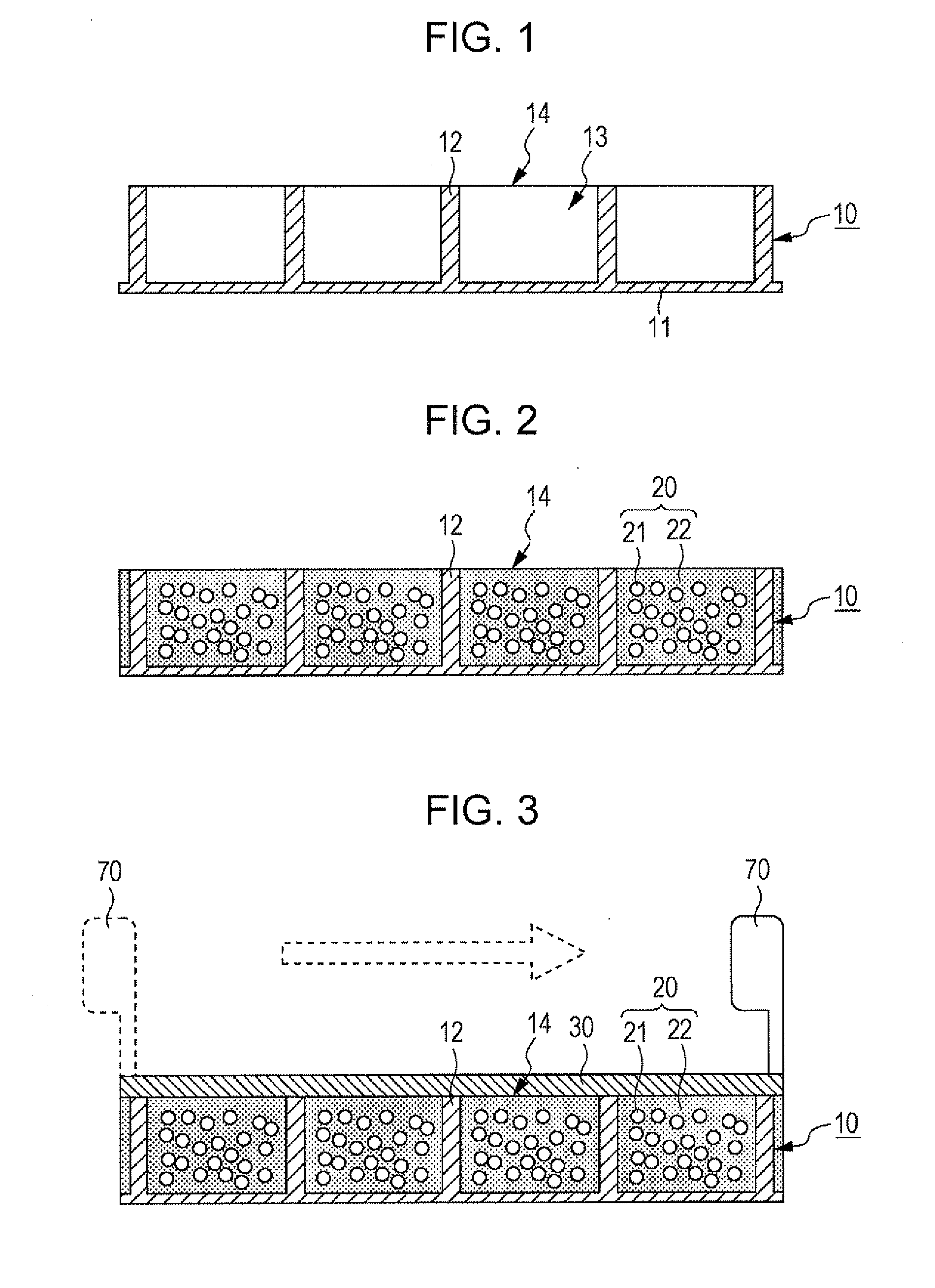
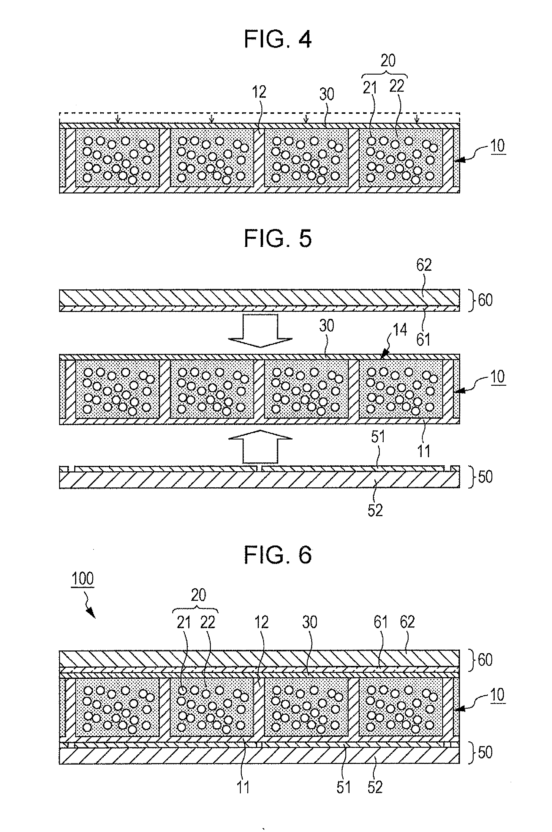
[0033]FIGS. 1 to 6 are diagrams illustrating the method for manufacturing an electrophoretic display apparatus 100 according to an embodiment of the invention.

[0034]As illustrated in FIG. 1, a structure 10 is first prepared to have a plurality of cells 13 spatially defined by partitions 12. (Hereinafter this structure is referred to as a cell matrix 10.) This cell matrix 10 has a flat substrate 11, and the partitions 12 are arranged on either side of this substrate 11. As illustrated in FIG. 7A, these partitions 12 divide the space on the substrate 11 to provide the cells 13. The partitions 12, on their plan view, are in a form such as a square grid. The cell matrix 10, which has the partitions 12 constituted as above, is made from a resin material such as epoxy resin, acrylic resin, urethane resin, melamine resin, or phenol resin, a ceramic material such as silica, alumina, or titania, or any other appropriate material.

[0035]FIGS. 1, 7A, and some other drawings i...

second embodiment

II. Second Embodiment

[0052]In the above-described first embodiment of the invention, a thickening agent may be added to the water-soluble polymer to increase the viscosity of the sealing coating. The second embodiment focuses on this point.

[0053]The following describes an exemplary combination, PVA chosen as the water-soluble polymer and boric acid (H3BO3) chosen as the thickening agent. A molecular structure of boric acid is illustrated in FIG. 8.

[0054]In the process of preparing the sealing solution, an aqueous solution containing PVA at a concentration in the range of 3 [wt %] to 40 [wt %] (hereinafter also referred to as the PVA aqueous solution) is combined with an aqueous solution of boric acid with the target concentration of boric acid set in the range of 2 [wt %] to 5 [wt %]. The aqueous solution of boric acid contains borate ions. As illustrated in FIG. 9, in the PVA aqueous solution borate ions link molecules of PVA (i.e., turn the PVA aqueous solution into a gel). This g...


PUM

PropertyMeasurementUnit
temperatureaaaaaaaaaa
optical transparencyaaaaaaaaaa
viscosityaaaaaaaaaa

Abstract

The following is included: loading cells spatially defined by partitions with a dispersion liquid containing electrophoretically mobile particles and a dispersion medium for dispersing the electrophoretically mobile particles, and covering the exposed surface of the dispersion liquid loaded in the cells with a sealing coating to seal the dispersion liquid in the cells. The dispersion medium is a lipophilic hydrocarbon solvent, and the sealing coating is made from a material containing a water-soluble polymer.

Description

CROSS-REFERENCE TO RELATED APPLICATION[0001]This application is based on and claims priority from Japanese Patent Application No. 2010-093210, filed on Apr. 14, 2010, the contents of which are incorporated herein by reference.BACKGROUND[0002]1. Technical Field[0003]The present invention relates to a method for manufacturing an electrophoretic display apparatus.[0004]2. Related Art[0005]It is generally known that applying an electric field to a liquid dispersion system containing dispersed fine particles makes the fine particles move (migrate) in the liquid through the action of Coulomb force. This phenomenon is referred to as electrophoresis, and recently electrophoretic display apparatuses, which make use of electrophoresis to display some desired information (image), have attracted public attention as a new generation of display apparatuses. The features of electrophoretic display apparatuses include the ability to hold the displayed information even with no voltage applied, a wid...

Claims


Application Information

Patent Timeline
Patent Type & Authority Applications(United States)
IPC IPC(8): B05D5/12G02F1/167G02F1/1679
CPCG02F1/167G02F2001/1678G02F2001/1672G02F1/1681G02F1/1679
Inventor SHITAGAMI, KOZOKOMATSU, HARUNOBU
Owner E INK CORPORATION
Learn More