Thermal diffusivity measuring system, concentration of caloric component measuring system, and flow rate measuring system

Inactive Publication Date: 2011-10-20
YAMATAKE HONEYWELL CO LTD
View PDF3 Cites 22 Cited by
  • Summary
  • Abstract
  • Description
  • Claims
  • Application Information

AI Technical Summary

Benefits of technology

[0058]The present invention provides a thermal diffusivity measuring system, a concentration of caloric component m

Problems solved by technology

Conventionally, it has been necessary to use costly gas chromatography equipment, or the like, to analyze the compliments of a mixed gas when calculating the amount of heat production of a mixed gas.
However, the method disclosed in JP '138 requires a costly speed-of-sound sensor to measure the speed of sound, in addition to a sensor for measuring the thermal conductivit

Method used


Image

  • Thermal diffusivity measuring system, concentration of caloric component measuring system, and flow rate measuring system
  • Thermal diffusivity measuring system, concentration of caloric component measuring system, and flow rate measuring system
  • Thermal diffusivity measuring system, concentration of caloric component measuring system, and flow rate measuring system

Examples


Example

[0106]Examples of the present invention are described below. In the descriptions of the drawings below, identical or similar components are indicated by identical or similar codes. Note that the diagrams are schematic. Consequently, specific measurements should be evaluated in light of the descriptions below. Furthermore, even within these drawings there may, of course, be portions having differing dimensional relationships and proportions.

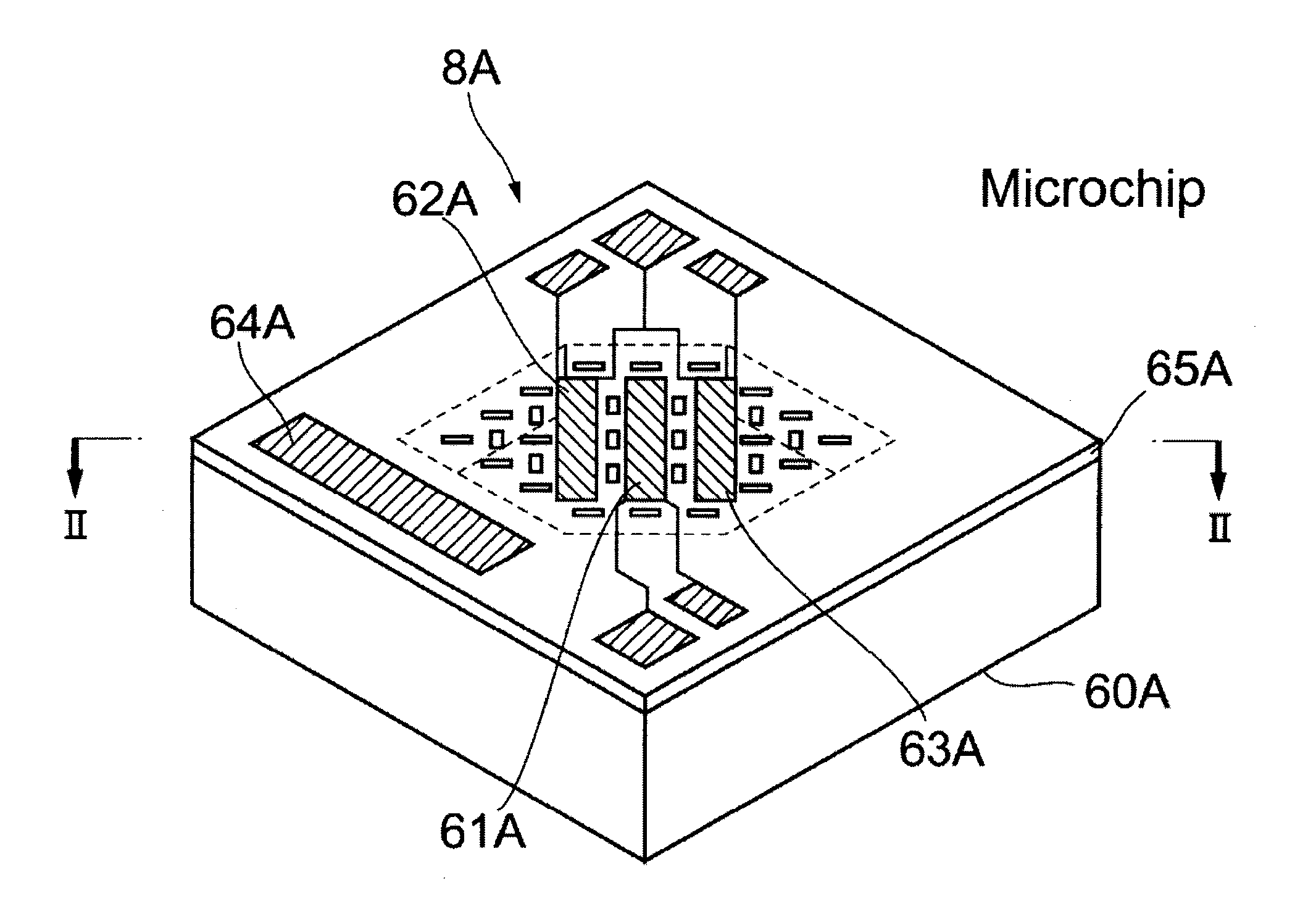
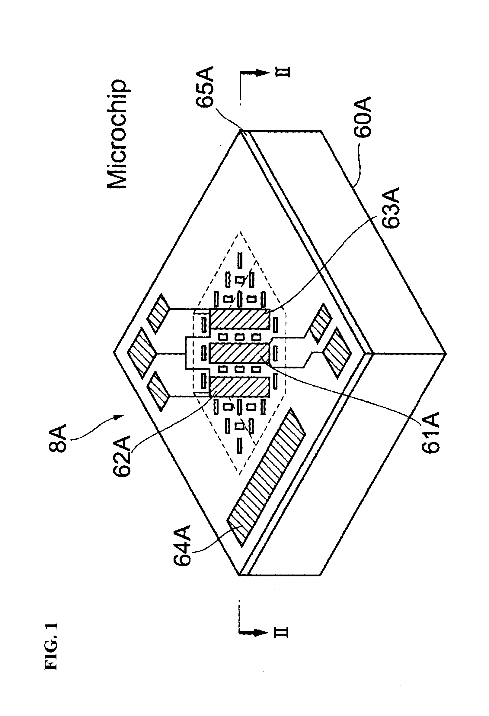
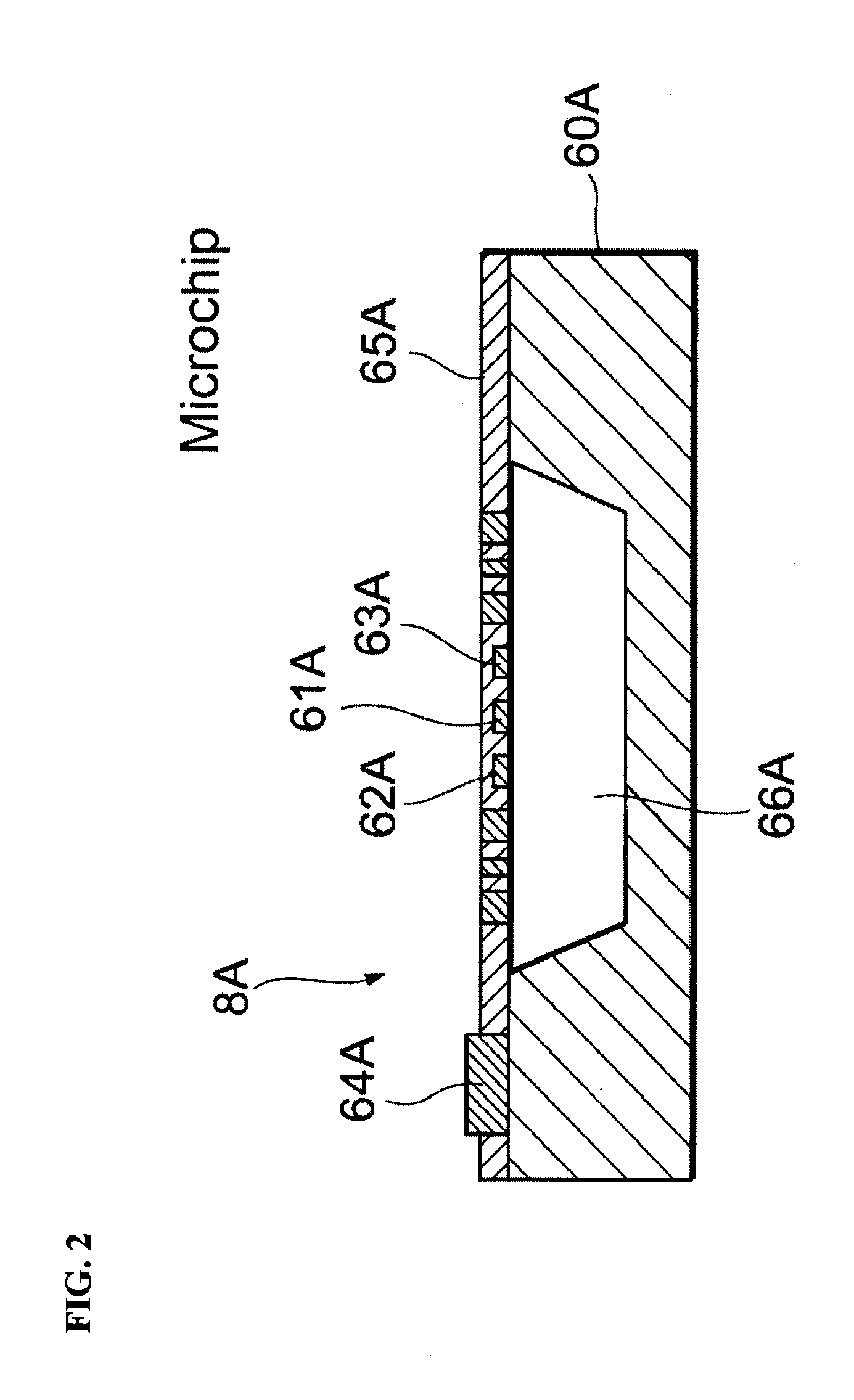
[0107]A microchip 8A that is used in a thermal diffusivity calculating equation generating system as set forth in an example is described in reference to FIG. 1, which is a perspective diagram, and FIG. 2, which is a cross-sectional diagram that is viewed from the direction of the section II-II, The microchip 8A comprises a substrate 60A, which is provided with a cavity 66A, and a dielectric layer 65A, which is disposed so as to cover the cavity 66A on the substrate 60A. The thickness of the substrate 60A is, for example, 0.5 mm. The length and wi...


PUM


Abstract

A thermal diffusivity measuring system including a measuring mechanism for measuring a radiation coefficient or a value for thermal conductivity for a mixed gas measured when the heater element has produced heat at a plurality of temperatures; a thermal diffusivity calculating equation storing device storing a thermal diffusivity calculating equation using the radiation coefficients or the thermal conductivities for a plurality of heat producing temperatures as independent variables and uses the thermal diffusivity as the dependent variable; and a thermal diffusivity calculating portion calculating a value for the thermal diffusivity of the mixed gas being measured through substituting the values of the radiation coefficients or the thermal conductivities of the mixed gas being measured, for the plurality of heat producing temperatures, for the independent variables of the radiation coefficients or thermal conductivities, for the plurality of heat producing temperatures, in the thermal diffusivity calculating equation.

Description

CROSS REFERENCE TO RELATED APPLICATIONS[0001]The present application claims priority under 35 U.S.C. §119 to Japanese Patent Application No. 2010-097139, filed Apr. 20, 2010, which is incorporated herein by reference.FIELD OF TECHNOLOGY[0002]The present invention relates to a thermal diffusivity measuring system, a concentration of caloric component measuring system, and a flow rate measuring system in relation to a gas inspection technology.BACKGROUND OF THE INVENTION[0003]Conventionally, it has been necessary to use costly gas chromatography equipment, or the like, to analyze the compliments of a mixed gas when calculating the amount of heat production of a mixed gas. Additionally, there have been proposals for a method for calculating the amount of heat production from a mixed gas by calculating the ratio of methane (CH4), propane (C3H8), nitrogen (N2), and carbon dioxide gas (CO2) components included in the mixed gas through measuring the thermal conductivity of the mixed gas an...

Claims


Application Information

Patent Timeline
IPC IPC(8): G01K17/00G06F19/00G01F1/00
CPCG01F1/6845G01N25/18G01F15/046G01F1/6965G01F25/15
Inventor OOISHI, YASUHARU
Owner YAMATAKE HONEYWELL CO LTD
Why Eureka
Try Eureka