Eureka AIR delivers breakthrough ideas for toughest innovation challenges, trusted by R&D personnel around the world.

Vaporizer

a technology of vaporizer and vaporizer body, applied in the direction of engine components, exhaust treatment, silting apparatus, etc., can solve the problems of difficult or impossible, vaporizers are not entirely functional,

Inactive Publication Date: 2011-10-27
DEUTZ AG
View PDF7 Cites 14 Cited by
  • Summary
  • Abstract
  • Description
  • Claims
  • Application Information

AI Technical Summary

Benefits of technology

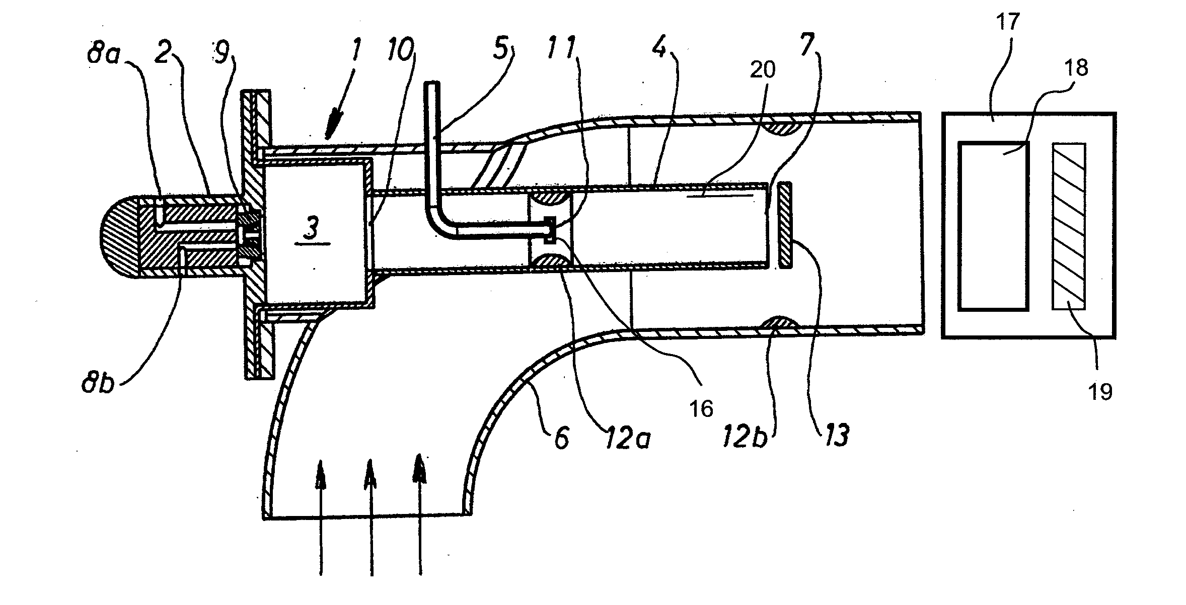
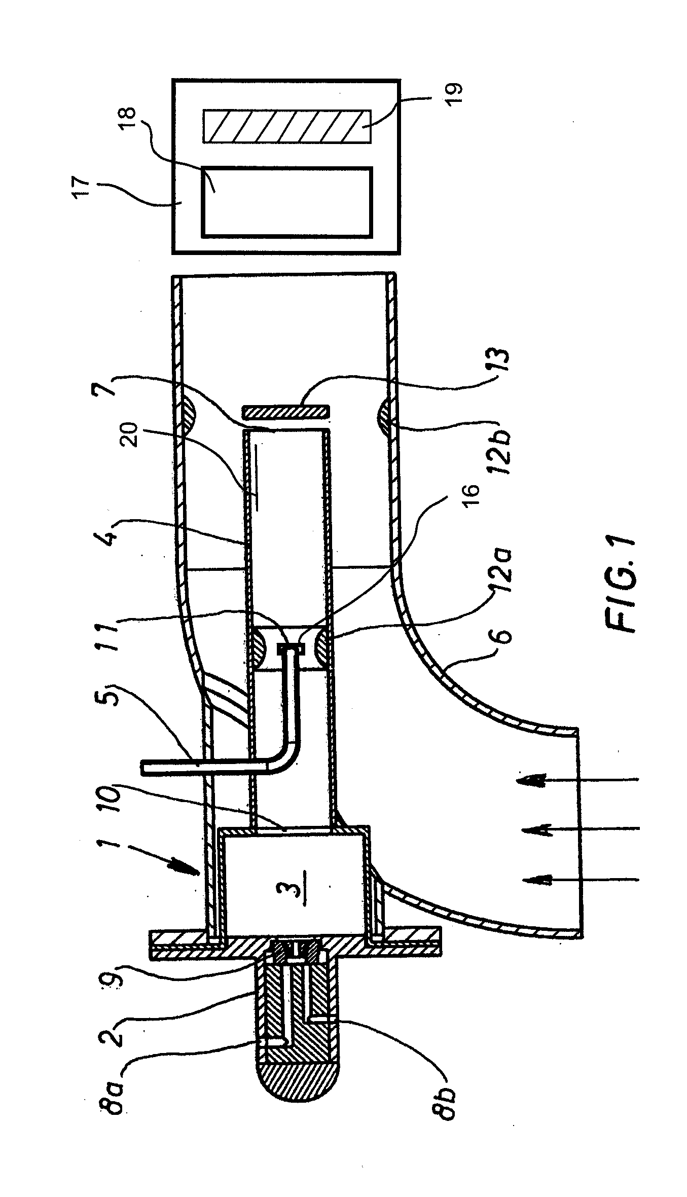
[0010]In a further embodiment, a venturi device is arranged in the exhaust duct near an opening of the introduction device. This effects a rapid mixing of the partial streams of exhaust gas and vaporizable liquid encountering each other.
[0013]In a further embodiment, the exhaust duct projects into the exhaust pipe with at least one port thereof. In this way, a good mixing of the converging streams of gas is ensured. For this purpose, the exhaust duct is preferably inserted concentrically into the exhaust pipe in such a manner that the port of the exhaust duct is arranged in the direction of the process exhaust gas stream, that is, for example, the internal combustion engine exhaust stream. This configuration achieves an increase in the velocity of flow of the process exhaust gas, which leads to a rapid mixing of the gas mixture, the same including the burner exhaust and the vapor (vaporized liquid), and the process exhaust. In this way, ignition of the gas mixture can be prevented if the process exhaust gas contains oxygen.
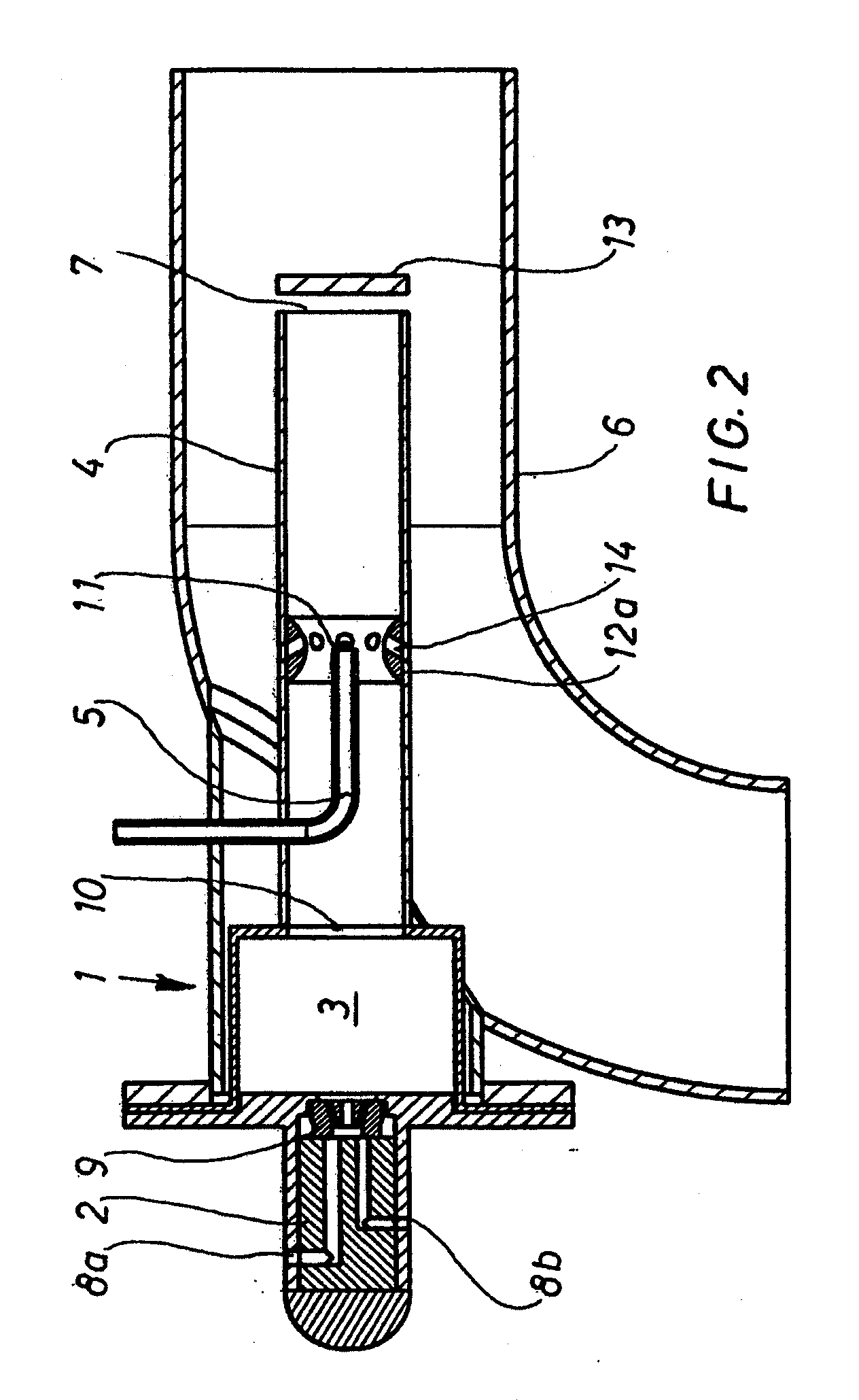
[0014]In order to further inhibit chemical reactions in the region of the inlet, appropriate auxiliary means can be provided which facilitate the same. Possible examples of such auxiliary means are, for example, a plate or a cone which is arranged before the port of the exhaust duct, wherein the tip of the cone is oriented facing the port of the exhaust duct. This configuration also provides a narrowing of the flow area in the region of the port, in addition or as an alternative to a further increase in the flow velocity, said narrowing being provided in the form of a venturi device or a venturi nozzle, for example. In other words, the configuration should quench a possible reaction between the process exhaust gas and the burner exhaust, the latter being prepared with vaporizable liquid.
[0016]In this way, the burner exhaust is cooled down in a controlled manner (where the feed is configured upstream from the opening of the feed inlet device in the direction of flow), and in such a manner that sufficient energy is provided for the purpose of vaporizing the vaporizable liquid, although the combustion of the same is prevented (if the vaporizable liquid is fuel). However, the feed can also be configured in the region of the opening, or downstream from the opening in the direction of flow. A chemical reaction between the vaporizable liquid and the burner exhaust and / or the process exhaust gas can be either facilitated or inhibited depending on requirements by means of appropriately selecting the described auxiliary means. Particularly by means of influencing the temperature in the region of the feed inlet device, it is possible to generate substances in a targeted manner by means of reactions between the vaporizable liquid and the burner exhaust, wherein said substances facilitate desired reactions in the downstream catalytic converters.
[0018]The constructive configurations described above are utilized in a reasonable manner for the purpose of implementing the further embodiment of the operating method according to the invention described below. As such, the burner is operated in a lambda range from 0.75 to 1.75, preferably at a lambda of 1. In addition, the burner is designed in such a manner that it can be operated in a power range up to 20 kW, preferably up to 15 kW, and most preferably up to 5 kW. It is one aim of the invention to operate the burner at the lower possible power, because particularly the air supply device required for the supply of (combustion-) air can then be designed with a relatively simple construction.
[0022]In an further embodiment of the method, a partial volume of the total volume of combustible fuel, the same being introduced as the vaporizable liquid and then vaporized, is oxidized within the exhaust duct and / or in the place where the same is brought together with the process exhaust, releasing heat. In this way, the total thermal energy provision is increased, coincident with burner performance adjusted to a minimal setting, to such a degree that the startup of a catalytic converter is ensured. In order to initiate the activity thereof, that is, in order to start a catalytic reaction of the introduced, vaporized fuel, an oxidative catalytic converter must achieve a prespecified minimum temperature, for example 300° C. This temperature is achieved by means of the total sum of energy from the burner and the energy generated by the combusted partial volume.

Problems solved by technology

Such vaporizers are not entirely functional in cases where process exhaust gas temperatures are low.
In many such cases, it is difficult or impossible, or is undesirable due to reasons of efficiency, to make the required amount of electrical energy available.

Method used


Image

  • Vaporizer
  • Vaporizer
  • Vaporizer

Examples


Embodiment Construction

[0029]For all embodiments, the vaporizer device has a housing 1, in which a burner 2, a combustion chamber 3, an exhaust duct 4, and an introduction device 5 for a vaporizable liquid are integrated. Here, the housing 1, likewise in all embodiments, is connected to an exhaust pipe 6 in such a manner that the exhaust duct 4, having a port 7, is inserted concentrically into the exhaust pipe 6, and the port 7 is arranged in the direction of the flow of the process exhaust gas flowing through the exhaust pipe 6.

[0030]The burner 2 has a supply device 8a for a gaseous or liquid combustible fuel, as well as a supply device 8b for air. The fuel and the air are mixed with each other in a suitable manner and introduced into the combustion chamber 3, for example via an air atomizing nozzle 9. The mixture is then combusted in the combustion chamber 3. For this purpose, the mixture in the burner 2 and / or the combustion chamber 3 is ignited in a suitable manner. In order to keep heat loss low, the...


PUM


Abstract

A vaporizer device which works together with an exhaust pipe carrying process exhaust gas. An exhaust duct of the vaporizer device opens into the exhaust pipe. The vaporizer device has a burner comprising an injection device for fuel and air, a combustion chamber, and the exhaust duct. An exhaust gas aftertreatment device is inserted into the exhaust pipe downstream of the junction with the exhaust duct. A method for the operation of such a vaporizer device. According to the invention, a vaporizer device and a method for the operation of such a vaporizer device are provided, and are expanded or improved with respect to the functionality thereof. This is achieved in that an introduction device for the vaporizable liquid is inserted into the exhaust duct. The corresponding method is characterized in that the burner provides sufficient thermal energy, wherein the lower limit thereof is prespecified by the provision of an amount of energy which is sufficient for the vaporization of an amount of vaporizable liquid which is larger than the amount of vaporizable liquid introduced into the exhaust duct.

Description

[0001]The invention relates to a vaporizer device which works together with an exhaust pipe carrying process exhaust gas, wherein an exhaust duct of the evaporator device opens into said exhaust pipe. The evaporator device has a burner comprising an injection device for fuel and air, a combustion chamber, and said exhaust duct. An exhaust gas aftertreatment device is inserted into the exhaust pipe downstream of the junction with the exhaust duct. The invention also relates to a method for the operation of such a vaporizer device.BACKGROUND[0002]Such a vaporizer device is known from DE 10 2004 048 336 A1. The vaporizer is inserted into the exhaust system of an internal combustion engine, wherein the internal combustion engine exhaust is discharged, and undesired emissions are reduced, by means of said exhaust system. In addition, a fuel feed device, an oxidative catalytic converter, and a particulate filter are arranged in the exhaust system. In order to improve the introduction of t...

Claims


Application Information

Patent Timeline
IPC IPC(8): F01N3/18F01N3/10
CPCF01N3/206F01N3/36F01N2240/14F01N2610/1453F01N2610/03F01N2610/06F01N2610/02
Inventor MIEBACH, ROLFSCHRAML, STEPHANBROLL, PETERSCHLUETER, DIRK
Owner DEUTZ AG
Why Eureka
Eureka Blog
Learn More