Lighting device, headlamp apparatus and vehicle using same

a technology of headlamps and lighting devices, which is applied in the direction of electric variable regulation, process and machine control, instruments, etc., can solve the problems of abnormality detection units b>56/b> being erroneously operated, failure of lighting devices, etc., and achieve the effect of preventing abnormal output voltage from increasing

Active Publication Date: 2011-10-27
PANASONIC CORP
View PDF5 Cites 41 Cited by
  • Summary
  • Abstract
  • Description
  • Claims
  • Application Information

AI Technical Summary

Benefits of technology

In view of the above, the present invention provides a lighting device capable of preventing an output voltage from abnormally increasing when the status of loads undergoes a change and a headlamp device and a motor vehicle using same.
The control unit may switch the power converting unit in a boundary conduction mode and prolongs the switching-off time of the power converting unit when the constant current control is switched to the constant voltage control.
The present invention has an advantage in that it is possible to prevent an output voltage from abnormally increasing when the status of loads undergoes a change.

Problems solved by technology

It is difficult to prevent occurrence of such phenomena.
The abnormal increase in the output voltage is likely to apply stresses to the circuit parts of the lighting device 1′, which may lead to failure of the lighting device 1′.
If the abnormality detecting unit 56 is allowed to stop the operation of the power converting unit 3 in response to the instantaneous increase in the output voltage, there is a possibility that the abnormality detecting unit 56 may be erroneously operated due to a noise or other causes.
Consequently, the output may become excessive because time required in determination gets longer.
The failure of the lighting device 1′ can be prevented by using high-voltage circuit parts, however, this may lead to an increase in the size cost of the lighting device 1′.
This also makes it difficult to balance the upper limit value Vmax of a normal range of the output voltage and the forward voltages Vf.

Method used


Image

  • Lighting device, headlamp apparatus and vehicle using same
  • Lighting device, headlamp apparatus and vehicle using same
  • Lighting device, headlamp apparatus and vehicle using same

Examples


first embodiment

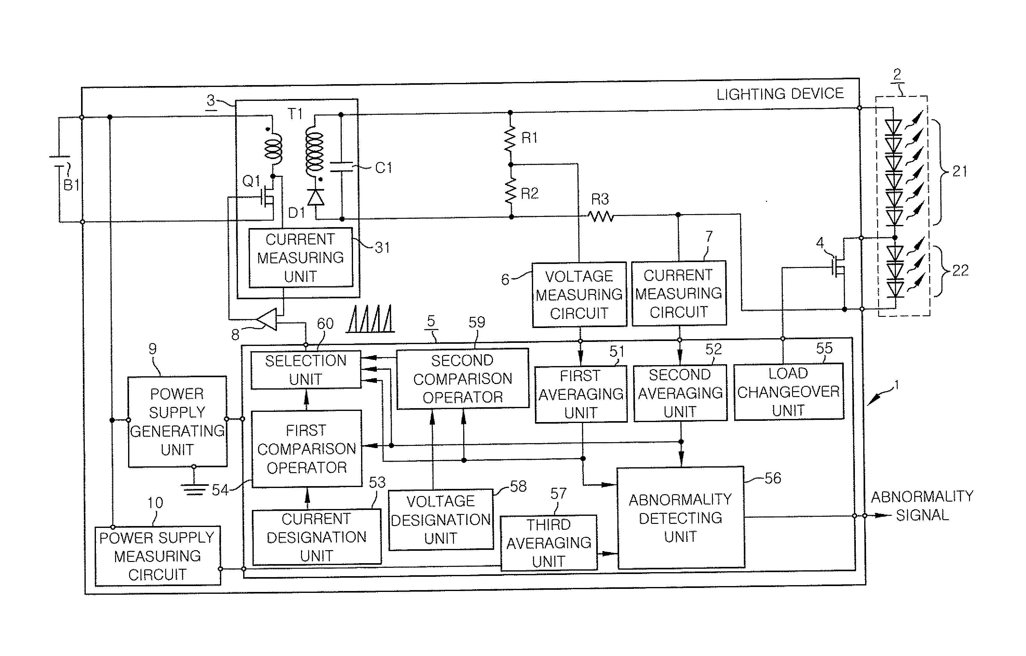
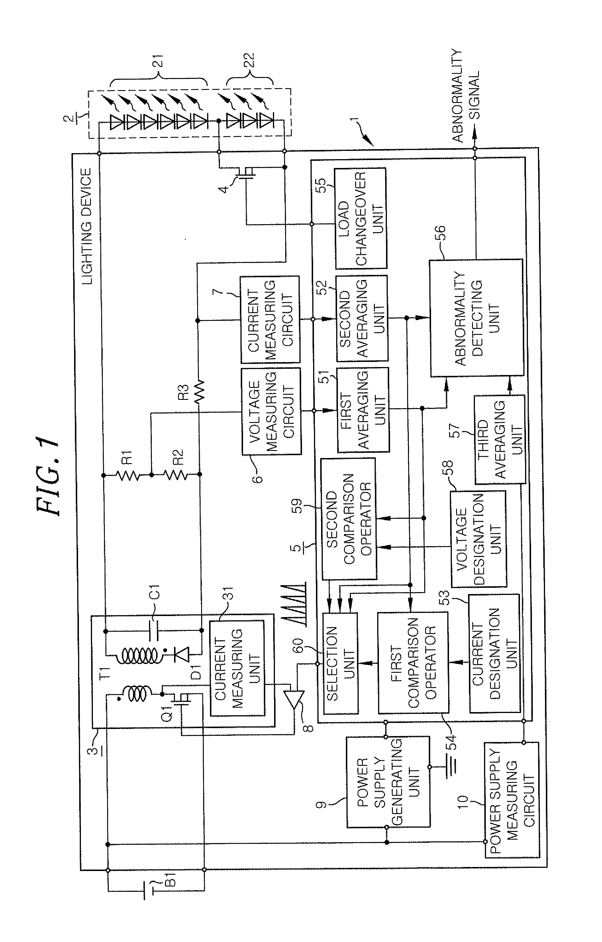
A lighting device of the present embodiment shares the basic configurations with the conventional lighting device 1′ shown in FIG. 18. The same configurations and functions as those of the conventional lighting device 1′ shown in FIG. 18 will be described first.

Referring to FIG. 1, the lighting device 1 in accordance with the present embodiment is designed to turn on loads 2 including a plurality of (e.g., nine, in the present embodiment) LEDs 21 and 22 serially-connected by applying a DC voltage to the loads 2. In the present embodiment, it is assumed that the lighting device 1 is installed in a motor vehicle. Among the LEDs 21 and 22 forming the loads 2, the six anode-side LEDs 21 are used as crossing headlights (also called low-beam headlamps) and the three cathode-side LEDs 22 are used as curvelights. The curve lamps referred to herein are so-called cornering lights. The curve lamps are auxiliary lights that turn on when a motor vehicle runs along a curved road with its headlamp...

second embodiment

The lighting device 1 of the present embodiment differs from the lighting device 1 of the first embodiment in that the power converting unit 3 is controlled in a BCM (Boundary Conduction Mode).

Referring to FIG. 8, the lighting device 1 of the present embodiment includes a drive circuit (DC) 61 having an RS flip-flop inserted between the output terminal of the comparator 8 and the switching element Q1 and a signal generating unit 62 for outputting an on-signal to the drive circuit 61. The drive circuit 61 has a set terminal to which the signal generating unit 62 is connected and a reset terminal to which the comparator 8 is connected. The signal generating unit 62 outputs an on-signal when the secondary coil current of the transformer T1 becomes zero (discharged). The secondary coil current becoming zero is detected by the current measuring unit 31 by using the decrease in the drain voltage of the switching element Q1 and is notified to the signal generating unit 62 as a discharge co...

third embodiment

The lighting device 1 of the present embodiment differs from the lighting device 1 of the second embodiment in that, as shown in FIG. 13B, there is an additional step of stopping the drive signal (step F36) when the output voltages are greater than the voltage designated value (step F35). Moreover, the lighting device 1 of the present embodiment is designed to return to the constant current control if a specific time (e.g., 10 ms) lapses after the switching to the constant voltage control (step F33) or if the output currents reach the switching current value (e.g., 0.4 A) (step F34). In FIG. 13B, the step of detecting the drive frequency (step F31) and the step of detecting the sudden change in the load status from the consecutive increase in the drive frequency (step F32) are the same as described above in the second embodiment.

(a), (b) and (c) of FIG. 14 show the changes of the output voltages, the output currents and the drive frequency of the switching element Q1 in the lighting...


PUM


Abstract

A lighting device includes: a power converting unit; a voltage measuring unit for measuring an output voltage from the power converting unit or a value equivalent to the output voltage; a current measuring unit for measuring an output current from the power converting unit or a value equivalent to the output current; and a control unit for controlling the power converting unit. When one of the output voltage and the output current of the power converting unit is changed by a specific magnitude per unit hour, the control unit determines that a change in a load status has occurred and controls the power converting unit by switching constant current control in which a measurement value of the current measuring unit is kept at a specific current designated value to constant voltage control in which a measurement value of the voltage measuring unit is kept at a specific voltage designated value.

Description

FIELD OF THE INVENTIONThe present invention relates to a lighting device for supplying an output power required in loads, a headlamp apparatus and a vehicle using same.BACKGROUND OF THE INVENTIONIn recent years, the light emission efficiency of a semiconductor light source such as an LED (light-emitting diode) and an organic EL element has been improved, and illumination devices employing the semiconductor light sources have been put into practical use. The improvement in the light emission efficiency of the semiconductor light source has been recognized in the field of motor vehicles. Commercially available are motor vehicles that make use of semiconductor light sources in headlamps, taillights or brakelight.In general, a lighting device for use in turning on a semiconductor light source is designed to turn on the semiconductor light sources through constant current control by which an electric current flowing to the semiconductor light sources is kept constant. This is to make uni...

Claims


Application Information

Patent Timeline
Patent Type & Authority Applications(United States)
IPC IPC(8): B60Q1/02H05B37/02H05B44/00
CPCH05B33/0842H02M3/33507H02M1/32H05B45/48Y02B20/30H05B45/375H05B45/3725H05B45/385H05B45/38
Inventor TANAKA, TOSHIFUMI
Owner PANASONIC CORP
Why Eureka
Try Eureka