Camera system with autonomous miniature camera and light source assembly and method for image enhancement

a technology of miniature cameras and cameras, applied in the field of cameras, can solve the problems of inability to adjust the angle of view or illumination without a new, lack of sufficient optical zoom, and inability to control the light intensity

Inactive Publication Date: 2011-10-27
RGT UNIV OF CALIFORNIA
View PDF5 Cites 73 Cited by
  • Summary
  • Abstract
  • Description
  • Claims
  • Application Information

AI Technical Summary

Benefits of technology

[0009]The present inventors have recognized that such an improved system and method for illumination can be provided through the use of one or more tunable lenses as part of the light source. Tunable lenses refer to lenses with variable focal distances, and one type of a tunable lens is a fluidic lens. By utilizing such tunable lenses, which in at least some embodiments are fluidic (or microfluidic) lenses, improved lighting particularly involving a timed radiation pattern and / or a controlled beam angle can be achieved.

Problems solved by technology

Disadvantages of this imaging device include its two-dimensional view, lack of sufficient optical zoom, inability to adjust its angle of view or angle of illumination without a new incision, inability to control light intensity, and restrictions on its movement due to its large size and external cables.
Lighting has been a challenge for laparoscopic cameras because they operate in an environment of extreme darkness where accessibility to sources of illumination is limited.
Although such camera features are extremely desirable insofar as they allow surgeons to obtain both the global and the detailed view of the patient's abdomen as well as a large working space to practice surgery, it results in more strict requirements on lighting.
For those cameras for which zoom is an option, when a surgeon wants to see the details of an organ in a zoom-in mode, the angle of illumination may be much greater than the camera's field-of-view and thus there is often insufficient lighting for the desired image resulting in poor quality of the acquired image.
On the other hand, when a surgeon operates the camera in zoom-out mode to achieve a wide field-of-view, the limited illumination angle of the light source may not cover the entire desired image area, leading to rapid fading of the acquired image towards the edge of the image field.
In addition, the center portion of the acquired image may he over illuminated and saturated, resulting in penalty in resolution and dynamic range.

Method used


Image

  • Camera system with autonomous miniature camera and light source assembly and method for image enhancement
  • Camera system with autonomous miniature camera and light source assembly and method for image enhancement
  • Camera system with autonomous miniature camera and light source assembly and method for image enhancement

Examples


Embodiment Construction

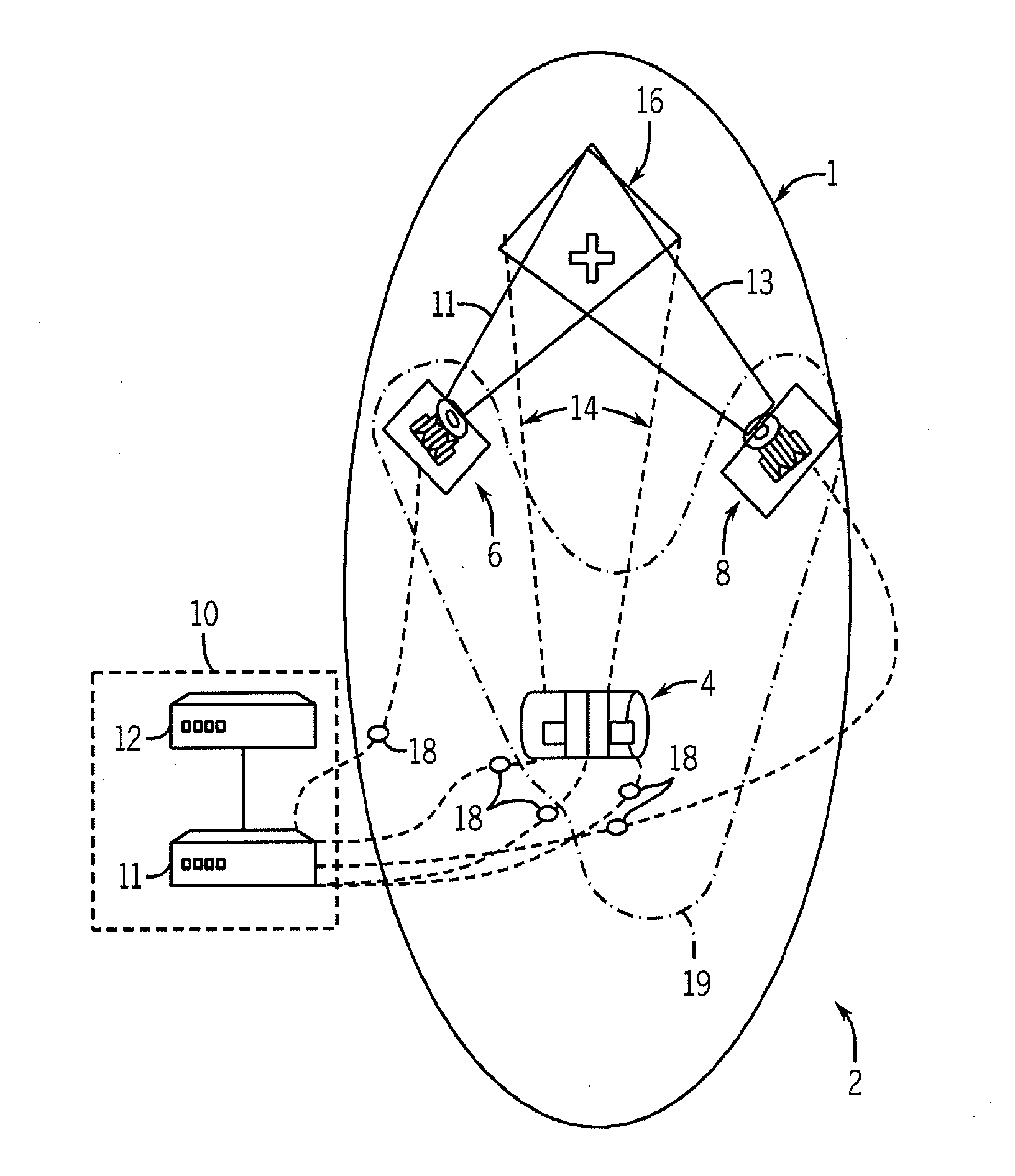
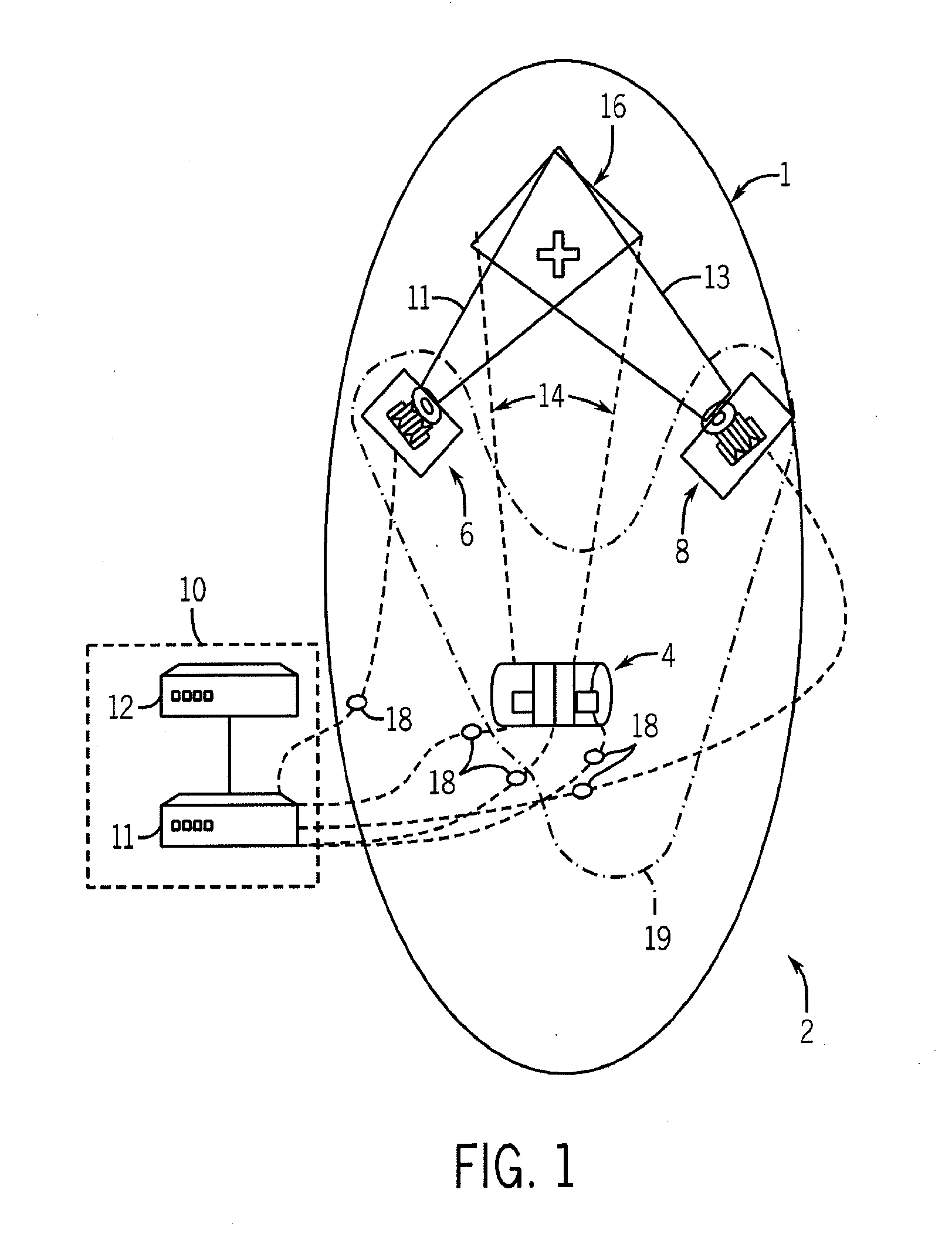
[0030]Referring to FIG. 1, an exemplary embodiment of a camera system 2 includes a miniature camera 4, two light source assemblies 6 and 8, respectively, and a control and processing unit 10 which includes a control unit 11 and a PZT (piezoelectric transducer) operator control unit 12 that are coupled to and in communication with one another. As shown schematically, the miniature camera 4 and light source assemblies 6, 8 are placed within an abdominal cavity 1 (or other body cavity or the like) of a patient, while the control and processing unit 10 remains exterior to the body of the patient. In at least one embodiment, the camera is insertable into an abdominal cavity through a 20 mm incision, such as on the abdominal wall, and the light source assembly is also insertable through an incision. In the present embodiment, it is envisioned that the miniature camera 4 is physically separated from each of the light source assemblies 6, 8, each of which is also physically separate from on...


PUM


Abstract

The present Invention relates to a camera system suitable for use in minimally invasive surgery (MIS), among other applications. In at least one embodiment, the camera system includes an autonomous miniature camera, a light source assembly providing features such as steerable illumination and a variable radiation angle, and a control and processing unit for processing images acquired by the camera Io generate improved images having reduced blurring using a deblurring algorithm.

Description

CROSS-REFERENCE TO RELATED APPLICATIONS[0001]This application claims the benefit of U.S. provisional patent application no, 61 / 105,542 entitled “Camera System With Autonomous Miniature Camera And Light Source Assembly And Method For Image Enhancement Using Color Correlation” filed on Oct. 15, 2008, which is hereby incorporated by reference herein.STATEMENT REGARDING FEDERALLY SPONSORED RESEARCH OR DEVELOPMENTFIELD OF THE INVENTION[0002]The present invention relates to camera systems and methods and, more particularly, to systems and methods of lighting that are employed as part of (or in combination with) such camera systems and methods in any of a variety of applications and environments including, for example, medical applications and environments,BACKGROUND OF THE INVENTION[0003]Minimally invasive surgery (MIS) is a modern surgical technique in which operations in the abdomen and thorax or elsewhere are performed through small incisions in the skin. Since 1981, when the first lap...

Claims


Application Information

Patent Timeline
Patent Type & Authority Applications(United States)
IPC IPC(8): H04N7/18
CPCA61B1/05A61B1/0676G03B15/05A61B19/5212A61B2019/521A61B1/0684A61B90/361A61B2090/309G03B2215/0528
Inventor LO, YU-HWAMINTZ, YOAVNGUYEN, TRUONGTZENG, JACK
Owner RGT UNIV OF CALIFORNIA
Why Eureka
Try Eureka