Microstructures for reducing noise of a fluid dynamic structure

a fluid dynamic structure and microstructure technology, applied in mechanical equipment, air-flow influencers, transportation and packaging, etc., can solve the problems of acoustic waves that manifest into broadband noise, scattering is a significant source of noise, and can cause significant noise, so as to reduce the resultant noise spectra, reduce the noise generated, and reduce the effect of fluid dynamic structure noise reduction

Active Publication Date: 2011-10-27
GENERAL ELECTRIC CO
View PDF4 Cites 78 Cited by
  • Summary
  • Abstract
  • Description
  • Claims
  • Application Information

AI Technical Summary

Benefits of technology

[0005]In one aspect of the invention, a fluid dynamic structure comprises a surface and a microstructure defined by a plurality of peaks and valleys on at least a portion of the surface. The microstructure includes a transition region in which each peak and valley changes from a first profile defined by a first spacing and a first height to a second profile defined by a second spacing and a second height at a predetermined distance along a chord length of the fluid dynamic structure, the second profile being different than the first profile, wherein the microstructure reduces noise generated by turbulent airflow across the fluid dynamic structure.
[0006]In another aspect of the invention, a fluid dynamic structure comprises a surface and a microstructure defined by a plurality of riblets on at least a portion of the surface. The plurality of riblets include a first profile in which each riblet has a first width and a first height at a first location along a chord length of said fluid dynamic structure, and a second profile in which each riblet has a second width and a second height at a second location along the chord length of the dynamic fluid structure, wherein the second profile is different than the first profile, and wherein the second location is different than the first location, and wherein the microstructure reduces noise generated by turbulent airflow across the fluid dynamic structure.

Problems solved by technology

The interaction of the energetic eddies with the walls of a fluid dynamic structure creates broadband noise.
For example, eddies from the turbulent boundary layer flow scatter are a significant source of noise when traveling past the trailing edge of airfoils.
When a lifting airfoil moves through a turbulent stream, an unsteady pressure field develops around the airfoil, which produces acoustic waves that manifest into broadband noise.
Such phenomena can readily be identified in nearly all types of vehicles, for example, automobiles, planes, helicopters, ships, submarines, and the like, the results of which can be quite troublesome.
For example, helicopter noise levels can easily approach 100 dB with a large portion of this noise related to the rotor blades cutting through the wake of the leading blade.
Sophisticated submarine propulsors, which are similar in form to an axial compressor in a turbofan engine, can produce considerable noise as the propulsor blades slice through boundary layer produced turbulence.
In combat scenarios, such noise levels obviously hamper the stealth capability of these vehicles.
In addition, with the passage of Bills, such as the “Silent Skies Act of 1999”, industry is increasingly coming under pressure to reduce the levels of noise pollution associated with turbomachinery propulsors (i.e. turbofans, turbojets, etc) on their aircraft.
Similarly wind turbine noise limits their public acceptance as well as the growth of the rotor to extract more renewable energy from the earth's wind resources; boundary layer noise, i.e, the interaction of turbulence in the boundary layers of the wind turbine blades with the airfoil surface, is one of the primary sources of wind turbine noise.

Method used


Image

  • Microstructures for reducing noise of a fluid dynamic structure
  • Microstructures for reducing noise of a fluid dynamic structure
  • Microstructures for reducing noise of a fluid dynamic structure

Examples


Embodiment Construction

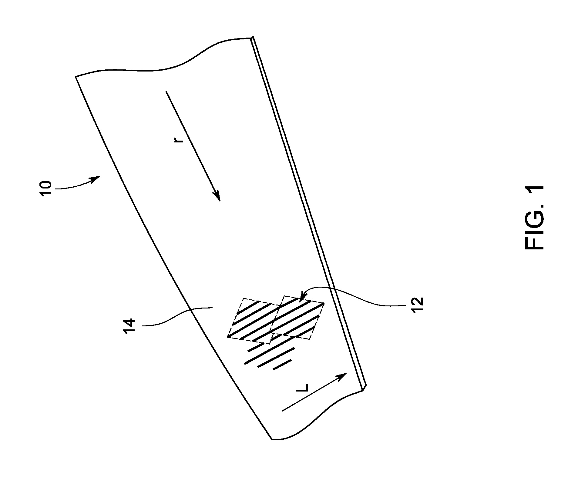
[0019]Referring now to FIG. 1, a fluid dynamic structure 10 includes a microstructure 12 mounted on a surface 14 of the structure 10 for reducing noise according to an embodiment of the invention.

[0020]In the illustrated embodiment, the fluid dynamic structure 10 comprises an airfoil. However, it will be appreciated that the fluid dynamic structure can be any structure designed for aerodynamics, such as a wind turbine blade, the internal and external surfaces of an aircraft engine, a wing of an aircraft, and the like. As used herein, a “microstructure” is a structure with a two-dimensional or three-dimensional profile in either a randomized or organized pattern, with each structure having a size of about 0.1 mm or less.

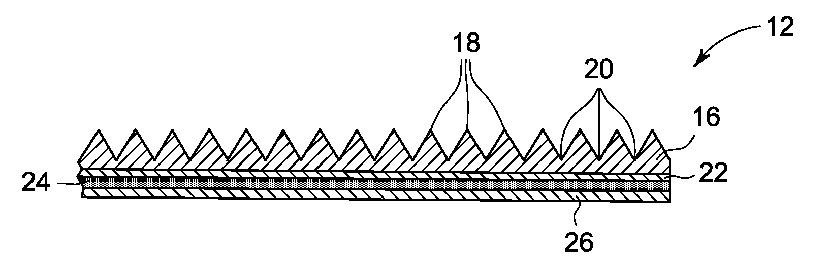
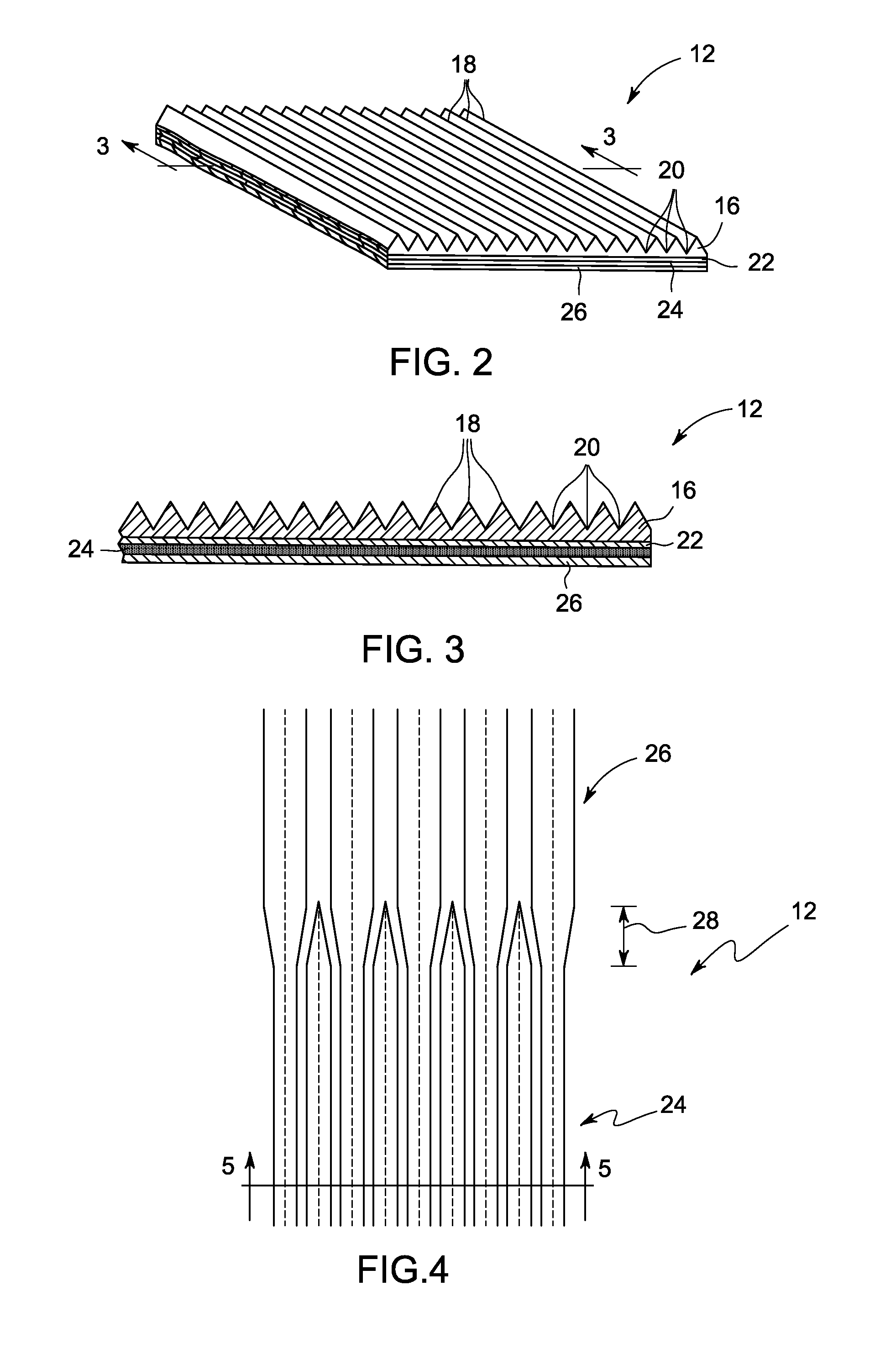
[0021]As shown in FIGS. 2 and 3, the microstructure 12 is in the form of small-size surface projections (so-called “riblets”) in which an array of small longitudinal ribs (peaks 18 and valleys 20) extending over the turbulent boundary layer region of the surface 14 in...


PUM

PropertyMeasurementUnit
sizeaaaaaaaaaa
taper angleaaaaaaaaaa

Abstract

A fluid dynamic structure includes a surface and a microstructure mounted on the surface. The microstructure is defined by a plurality of peaks and valleys (i.e., riblets) and includes a transition region in which each peak and valley changes from a first profile to a second profile along a chord length of the structure. The peaks and / or valleys may have a variable dimension along the length of the microstructure. The peaks and valleys can be non-linear along the chord length and have a smooth transition from the first profile to the second profile. The different profiles of the microstructure are optimized to reduce noise generated by turbulent fluid flow across the structure.

Description

BACKGROUND OF THE INVENTION[0001]In fluid dynamics, turbulence or turbulent flow is a fluid regime characterized by chaotic, stochastic property changes. This includes low momentum diffusion, high momentum convection, and rapid variation of pressure and velocity in space and time.[0002]Turbulence causes the formation of eddies of many different length scales. Most of the kinetic energy of the turbulent motion is contained in the large-scale structures. The energy “cascades” from these large scale structures to smaller scale structures by an inertial and essentially inviscid mechanism. This process continues creating smaller and smaller structures that produces a hierarchy of eddies. Eventually this process creates structures that are small enough that molecular diffusion becomes important and viscous dissipation of energy finally takes place. The scale at which this happens is the Kolmogorov length scale.[0003]The interaction of the energetic eddies with the walls of a fluid dynamic...

Claims


Application Information

Patent Timeline
Patent Type & Authority Applications(United States)
IPC IPC(8): B32B3/00
CPCB64C21/10F15D1/004Y02T50/166Y10T428/2457Y10T428/24744Y10T428/24479B64C2230/26Y02T50/10Y02E10/72
Inventor GUPTA, ANURAGMILLER, SCOTT MICHAELMAEDER, THIERRY
Owner GENERAL ELECTRIC CO
Why Eureka
Try Eureka