Coolant circuit for an internal combustion engine

a technology of internal combustion engine and cooling circuit, which is applied in the direction of machines/engines, mechanical equipment, cylinders, etc., can solve the problems of slowing down the heating of the cylinder block, and achieve the effect of quick and evenly heated

Active Publication Date: 2011-11-03
AUDI AG
View PDF5 Cites 3 Cited by
  • Summary
  • Abstract
  • Description
  • Claims
  • Application Information

AI Technical Summary

Benefits of technology

[0012]According to another advantageous feature of the present invention, a second control valve can be arranged in the common lead flow section between the main heat exchanger and the coolant pump, and a branch line may extend from the common return flow to the second control valve to bypass the main heat exchanger. The branch line optionally allows a bypass of the main heat exchanger, when appropriately switching the second control valve. In the bypass operation, a coolant flow can be established in the cylinder heads and in dependence on the first control valve also in the cylinder crankcase, without cooling down the hea

Problems solved by technology

This causes an undesired coolant movement in the cylinder cooling jacket as a

Method used


Image

  • Coolant circuit for an internal combustion engine
  • Coolant circuit for an internal combustion engine

Examples


Embodiment Construction

[0014]The depicted embodiment is to be understood as illustrative of the invention and not as limiting in any way. It should also be understood that the figure is not necessarily to scale and that embodiments are sometimes illustrated by graphic symbols, phantom lines, diagrammatic representations and fragmentary views. In certain instances, details which are not necessary for an understanding of the present invention or which render other details difficult to perceive may have been omitted.

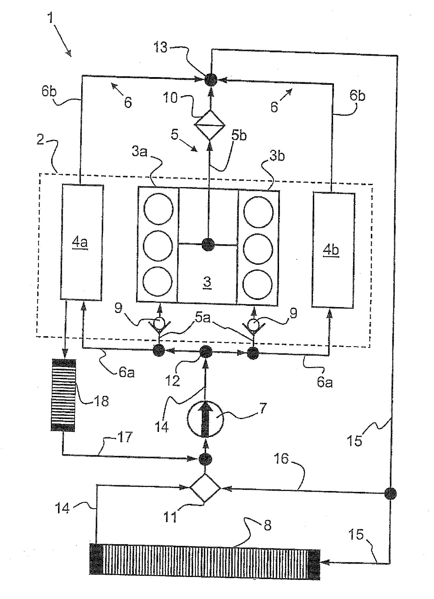
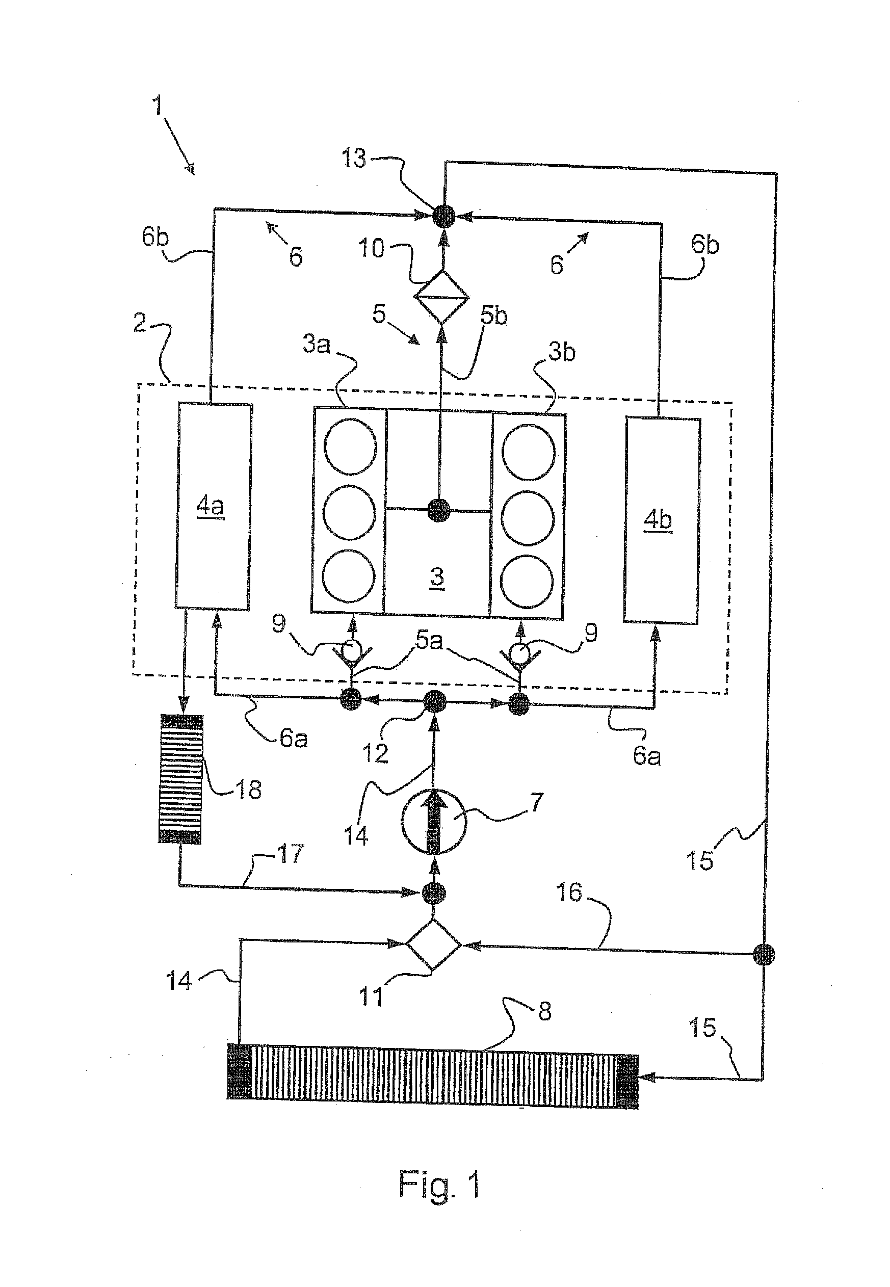
[0015]Turning now to FIG. 1, there is shown a schematic illustration of a coolant circuit according to the present invention, generally designated by reference numeral 1, for an internal combustion engine 2. The coolant circuit 1 includes a coolant pump 7 for producing a coolant circulation in the coolant circuit 1, and a main heat exchanger 8 for heat exchange between ambient air sweeping about the main heat exchanger 8 and coolant flowing through the main heat exchanger 8. The internal combusti...


PUM


Abstract

A coolant circuit for an internal combustion engine having a cylinder crankcase with at least two opposing cylinder banks, and cylinder heads associated to the cylinder banks, includes a first subcircuit for cooling the cylinder crankcase and a second subcircuit in separate parallel relationship to the first subcircuit for cooling the cylinder heads. A coolant pump circulates a coolant at least temporarily between a main heat exchanger and the cylinder heads and/or cylinder crankcase. At least one check valve is arranged in the first subcircuit to allow a flow of coolant through the cylinder banks only in a direction from an intake side to an exhaust side.

Description

CROSS-REFERENCES TO RELATED APPLICATIONS[0001]This application claims the priority of German Patent Application, Serial No. 10 2010 018 624.4, filed Apr. 28, 2010, pursuant to 35 U.S.C. 119(a)-(d), the content of which is incorporated herein by reference in its entirety as if fully set forth herein.BACKGROUND OF THE INVENTION[0002]The present invention relates to a coolant circuit for an internal combustion engine.[0003]The following discussion of related art is provided to assist the reader in understanding the advantages of the invention, and is not to be construed as an admission that this related art is prior art to this invention.[0004]Coolant circuits are typically used in internal combustion engines for motor vehicles for cooling components of the internal combustion engine, for example cylinder heads and cylinder crankcases, to a different temperature level. An example of a coolant circuit involves a construction in two-circuit cooling configuration for an internal combustio...

Claims


Application Information

Patent Timeline
IPC IPC(8): F01P7/14
CPCF01P3/02F02F7/0012F01P2060/08F01P2003/027F02F1/14F02F1/40
Inventor HONZEN, MATTHIASANTON, CHRISTOPHRIEDL, SEBASTIAN
Owner AUDI AG
Why Eureka
Try Eureka