Permanent magnet and process for producing permanent magnet

a permanent magnet and permanent magnet technology, applied in the field of permanent magnets, can solve the problems of grain growth of magnet particles, insufficient inhibition of grain growth at the time of sintering, etc., and achieve the effects of improving magnetic performance, preventing oxidation of pulverized magnet raw materials, and improving the magnetic performan

Inactive Publication Date: 2011-11-03
NITTO DENKO CORP
View PDF6 Cites 25 Cited by
  • Summary
  • Abstract
  • Description
  • Claims
  • Application Information

AI Technical Summary

Benefits of technology

On the other hand, it has been known that the magnetic characteristics of the permanent magnet are basically improved by miniaturizing the crystal grain size of a sintered body, because the magnetic characteristics of the magnet is derived by a single-domain fine particle theory. In general, when the crystal grain size of the sintered body is adjusted to 3 μm or less, it becomes possible to sufficiently improve the magnetic performance.
The invention has been made in order to solve the above-mentioned conventional problems, and an object of the invention is to provide a permanent magnet in which oxidation of a pulverized magnet raw material can be prevented by mixing the magnet raw material with a rust preventive oil and in which the crystal grain size of the sintered body is adjusted to 3 μm or less to make it possible to improve the magnetic performance, because the grain growth of the magnet particles at the time of sintering can be inhibited by a high-melting metal element-containing organic compound or a precursor of a high-melting ceramic dissolved in the mixed rust preventive oil; and a method for manufacturing the permanent magnet.
According to the permanent magnet having the constitution of the above (1), oxidation of the pulverized magnet raw material can be prevented by mixing the magnet raw material with the rust preventive oil. Further, the grain growth of the magnet particles at the time of sintering can be inhibited by coating the surfaces of the pulverized magnet particles with the high-melting metal element-containing organic compound or the precursor of the high-melting ceramic dissolved in the mixed rust preventive oil. Accordingly, it becomes possible to adjust the crystal grain size of the sintered body to 3 μm or less to improve the magnetic performance.
Further, according to the permanent magnet described in the above (2), the high-melting metal element-containing organic compound or the precursor of the high-melting ceramic is unevenly distributed in the grain boundary of the magnet raw material after sintering, so that it becomes possible to inhibit the grain growth of the magnet particles at the time of sintering without decreasing the residual magnetization of the magnet.
Furthermore, according to the method for manufacturing a permanent magnet described in the above (3), oxidation of the pulverized magnet raw material can be prevented by mixing the magnet raw material with the rust preventive oil. In addition, the grain growth of the magnet particles at the time of sintering can be inhibited by coating the surfaces of the pulverized magnet particles with the high-melting metal element-containing organic compound or the precursor of the high-melting ceramic dissolved in the mixed rust preventive oil. Accordingly, it becomes possible to adjust the crystal grain size of the sintered body to 3 μm or less to improve the magnetic performance.

Problems solved by technology

However, even when the magnet raw material finely pulverized to a grain size of 3 μm or less is molded and sintered, grain growth of magnet particles occurs at the time of sintering.
As a result, the grain growth at the time of sintering cannot be sufficiently inhibited.

Method used


Image

  • Permanent magnet and process for producing permanent magnet
  • Permanent magnet and process for producing permanent magnet
  • Permanent magnet and process for producing permanent magnet

Examples


Embodiment Construction

A specific embodiment of a permanent magnet and a method for manufacturing the permanent magnet according to the invention will be described below in detail with reference to the drawings.

Constitution of Permanent Magnet

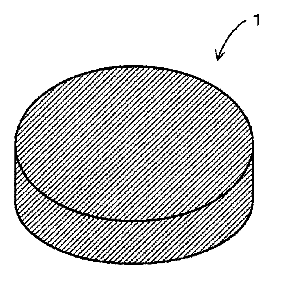
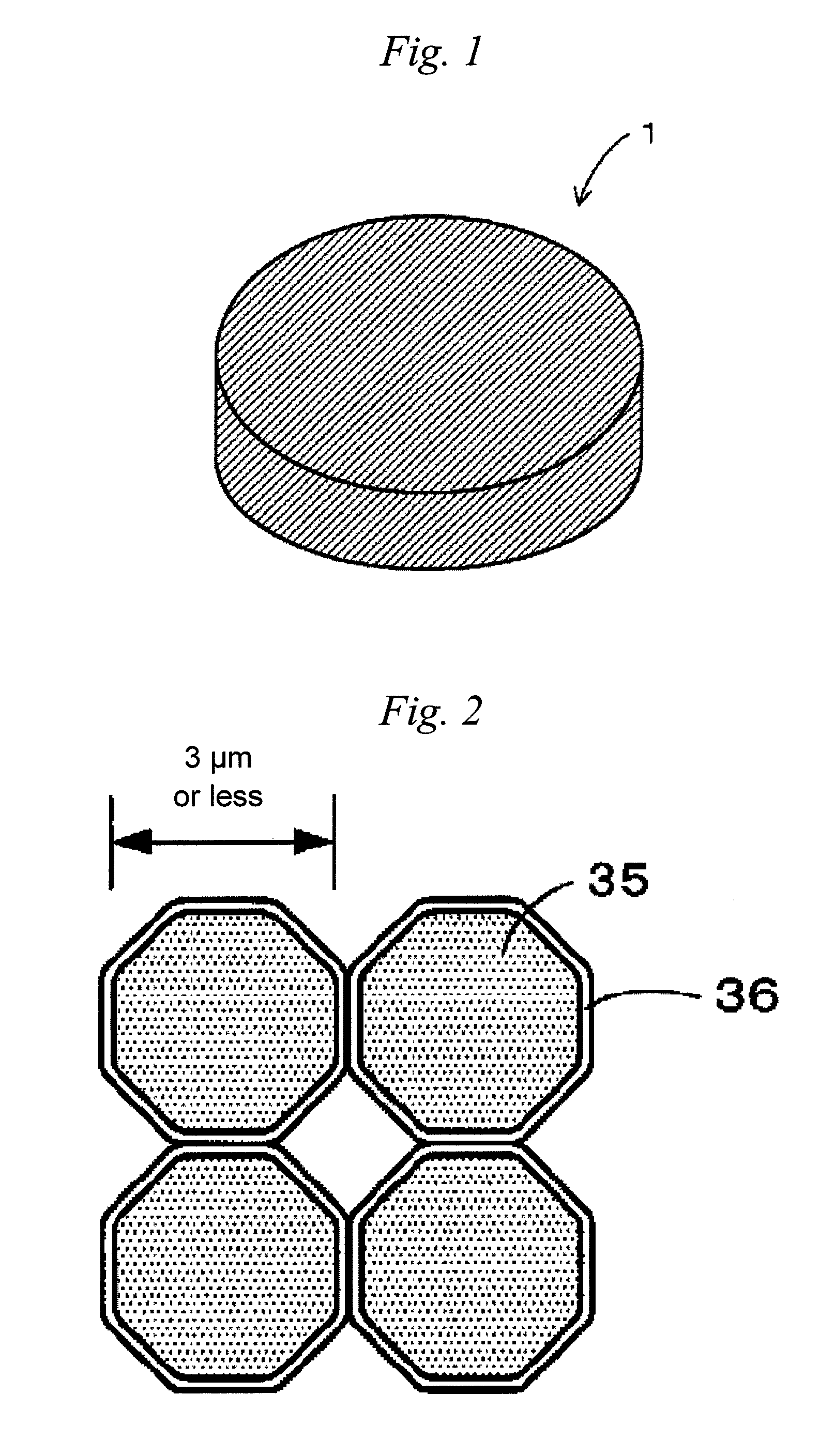
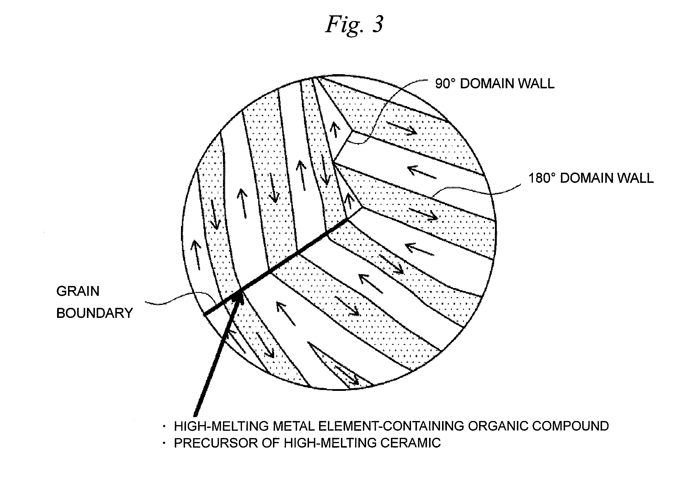
First, a constitution of a permanent magnet 1 will be described using FIGS. 1 to 3.

The permanent magnet 1 according to this embodiment is a Nd—Fe—B-based magnet. Further, a high-melting metal element-containing organic compound or a precursor of a high-melting ceramic for inhibiting the grain growth of the permanent magnet 1 at the time of sintering is added. Incidentally, the contents of respective components are regarded as Nd: 27 to 30 wt %, a metal component contained in the high-melting metal element-containing organic compound (or a ceramic component contained in the precursor of the high-melting ceramic): 0.01 to 8 wt %, B: 1 to 2 wt %, and Fe (electrolytic iron): 60 to 70 wt %. Furthermore, the permanent magnet 1 according to this embodiment has a cylindrical...


PUM

PropertyMeasurementUnit
grain sizeaaaaaaaaaa
crystal grain sizeaaaaaaaaaa
grain sizeaaaaaaaaaa

Abstract

The present invention relates to a permanent magnet manufactured by steps of: pulverizing a magnet raw material into fine particles having a grain size of 3 μm or less; mixing the pulverized magnet raw material with a rust preventive oil in which a high-melting metal element-containing organic compound or a precursor of a high-melting ceramic is dissolved, thereby preparing a slurry; compression molding the slurry to form a molded body; and sintering the molded body.

Description

TECHNICAL FIELDThe present invention relates to a permanent magnet and a method for manufacturing the permanent magnet.BACKGROUND ARTIn recent years, a reduction in size and weight, an increase in power and an increase in efficiency have been required for permanent magnetic motors used in hybrid cars, hard disk drives or the like. Then, in realizing a reduction in size and weight, an increase in power and an increase in efficiency in the above-mentioned permanent magnetic motors, a reduction in film thickness and further improvement in magnetic characteristics have been required for permanent magnets buried in the permanent magnetic motors. Incidentally, as the permanent magnets, there are ferrite magnets, Sm—Co-based magnets, Nd—Fe—B-based magnets, Sm2Fe17Nx-based magnets and the like. In particular, Nd—Fe—B-based magnets having high coercive force are used as the permanent magnets for the permanent magnet motors.Here, as a method for manufacturing the permanent magnet, a powder si...

Claims


Application Information

Patent Timeline
Patent Type & Authority Applications(United States)
IPC IPC(8): H01F7/02C04B35/64B22F1/107
CPCB22F1/0074B22F2998/10C22C38/002C22C38/005H01F1/0552H01F1/0557H01F1/0572H01F41/0266H01F1/0577B22F9/04B22F1/0059B22F3/087B22F3/10B22F1/107
Inventor OZEKI, IZUMIKUME, KATSUYANAKAYAMA, JUNICHIFUKUDA, YUUKIHOSHINO, TOSHINOBUHORIO, TOMOKAZU
Owner NITTO DENKO CORP
Why Eureka
Try Eureka