Compact directional coupler using semiconductor process and mobile RFID reader transceiver system using the same

Inactive Publication Date: 2011-11-03
KOREA ADVANCED INST OF SCI & TECH
View PDF17 Cites 27 Cited by
  • Summary
  • Abstract
  • Description
  • Claims
  • Application Information

AI Technical Summary

Benefits of technology

[0009]Accordingly, the present invention has been made keeping in mind the above problems occurring in the prior art, and an object of the present invention is to provide a mobile RFI

Problems solved by technology

However, circulators have the disadvantages of being large, the isolation between ports being deteriorated, and being high-pric

Method used


Image

  • Compact directional coupler using semiconductor process and mobile RFID reader transceiver system using the same
  • Compact directional coupler using semiconductor process and mobile RFID reader transceiver system using the same
  • Compact directional coupler using semiconductor process and mobile RFID reader transceiver system using the same

Examples


first embodiment

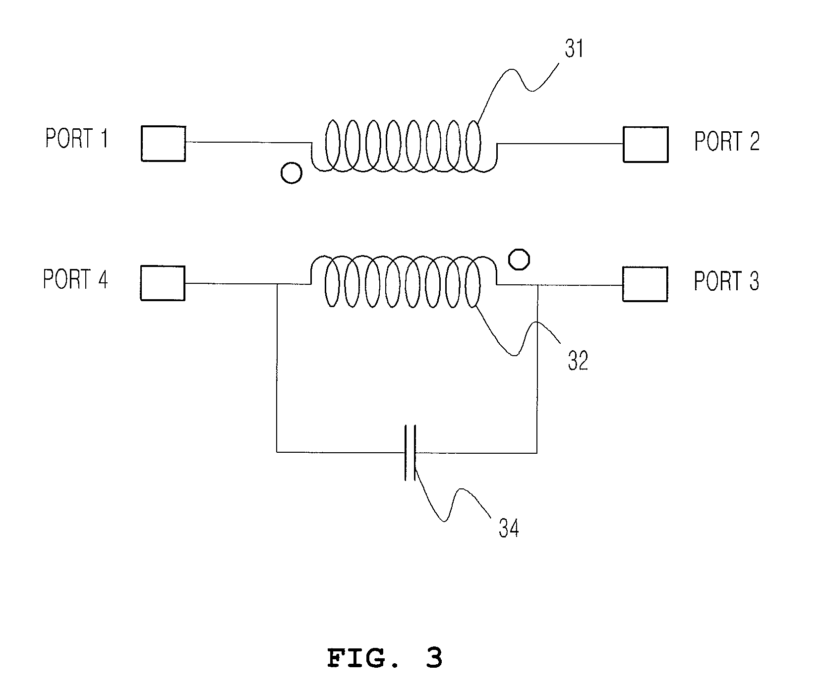
[0042]FIG. 3 is a circuit diagram showing a compact directional coupler according to the present invention.

[0043]As shown in FIG. 3, the compact directional coupler of the present invention includes a primary transmission line 31, a secondary transmission line 32, and a second capacitor 34 which is connected in parallel with the secondary transmission line 32.

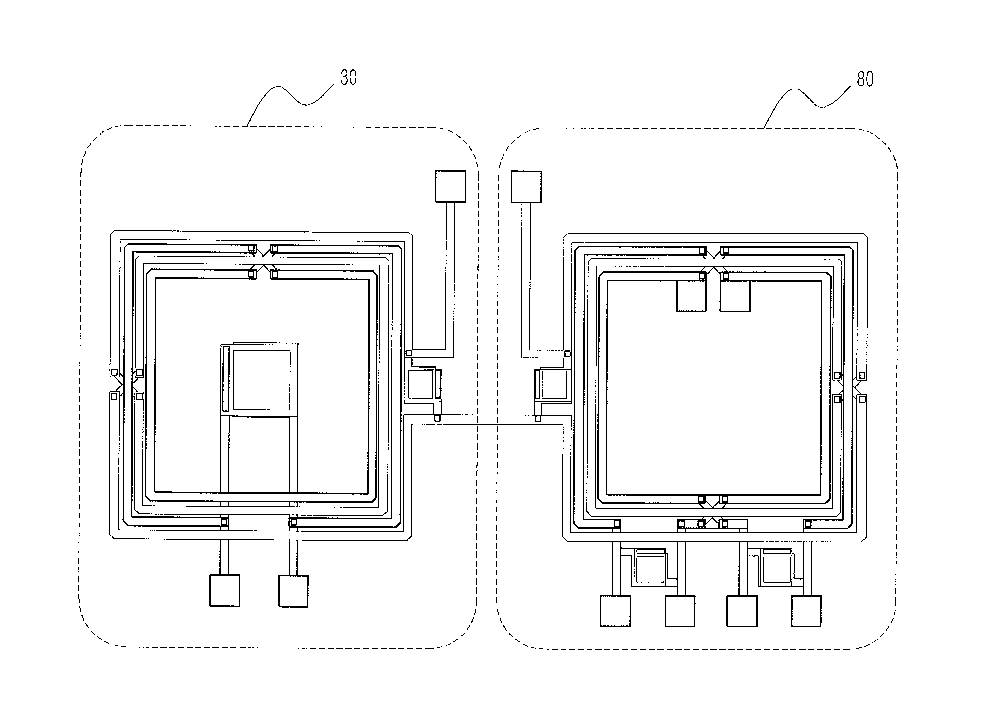
[0044]FIG. 4 is a view showing the layout of the circuit diagram of FIG. 3.

[0045]The elements of the compact directional coupler of the present invention will be described in detail with reference to FIGS. 3 and 4.

[0046]The primary transmission line 31 can be formed so that a signal is transmitted therethrough, and the secondary transmission line 32 can be formed as a transmission line for coupling in such a way that the secondary transmission line 32 is adjacent to the primary transmission line 31 so as to extract some of the power of the signal transmitted through the primary transmission line 31. Further, the primary transmi...

second embodiment

[0053]FIG. 5 is a circuit diagram showing a compact directional coupler according to the present invention, and FIG. 6 is a view showing the layout of the circuit diagram of FIG. 5.

[0054]That is, as compared with FIGS. 3 and 4, FIGS. 5 and 6 show that the compact directional coupler also can include a first capacitor 33 connected in parallel with the primary transmission line 31. Further, the capacitance of the first capacitor 33 is less than that of the second capacitor 34.

third embodiment

[0055]FIG. 7 is a circuit diagram showing a compact directional coupler according to the present invention, and FIG. 8 is a view showing the layout of the circuit diagram of FIG. 7.

[0056]That is, for the purpose of impedance matching, the compact directional coupler also can include a third capacitor 35, arranged between the one port of the primary transmission line 31 and the ground, and a fourth capacitor 36, arranged between the remaining port of the primary transmission line 31 and the ground.

[0057]FIGS. 9 and 10 are views showing the examples of various layouts of the circuit diagram according to the second embodiment of FIG. 5.

[0058]That is, FIG. 9 shows two ports of the secondary transmission line 32 which are arranged to face the two ports of the primary transmission line 31. Unlike FIG. 9, in which the second capacitor 34 connected between the two ports of the secondary transmission line 32 is arranged inside of the transmission line transformer, FIG. 10 is a view showing t...


PUM


Abstract

A compact directional coupler and a mobile Radio-Frequency Identification (RFID) reader transceiver system using the same. The compact directional coupler can include a primary transmission line, a secondary transmission line, and a second capacitor connected in parallel to the secondary transmission line. The coupler can further include a first capacitor connected in parallel to the primary transmission line and capacitors connected between both end of the first capacitors and the ground respectively. A mobile RFID reader transceiver system can include a transmission terminal circuit, a power amplifier, the compact directional coupler, an antenna, a low noise amplifier, and the reception terminal circuit. The system further can include a band-pass filer, and/or a power combiner to match an output terminal of the power amplifier.

Description

CROSS-REFERENCE TO RELATED APPLICATIONS[0001]The present application claims priority under 35 U.S.C. 119 of Korean Patent Application No. 10-2010-0041269, filed on May 3, 2010, the disclosure of which is expressly incorporated by reference herein in its entirety.BACKGROUND OF THE INVENTION[0002]1. Field of the Invention[0003]The present invention relates generally to a directional coupler and a mobile Radio-Frequency Identification (RFID) reader transceiver system using the same, and, more particularly, to a compact directional coupler using a semiconductor process and a mobile RFID reader transceiver system using the same.[0004]2. Description of the Related Art[0005]RFID is a system which receives and decodes a signal and then detects the information of a corresponding tag when a wireless signal is transmitted from a reader and reaches a tag, and the wireless signal is modulated and returns to the reader. Fixed RFID readers have been widely used in logistics, traffic and distributi...

Claims


Application Information

Patent Timeline
IPC IPC(8): H01P5/18G08B13/14
CPCH01P5/185
Inventor HONG, SONG CHEOLSHIM, SUN BO
Owner KOREA ADVANCED INST OF SCI & TECH
Why Eureka
Try Eureka