

Tunable multiple laser pulse scanning microscope and method of operating the same
Active Publication Date: 2011-11-10
LEICA MICROSYSTEMS CMS GMBH
View PDF3 Cites 21 Cited by
- Summary
- Abstract
- Description
- Claims
- Application Information
AI Technical Summary
Benefits of technology
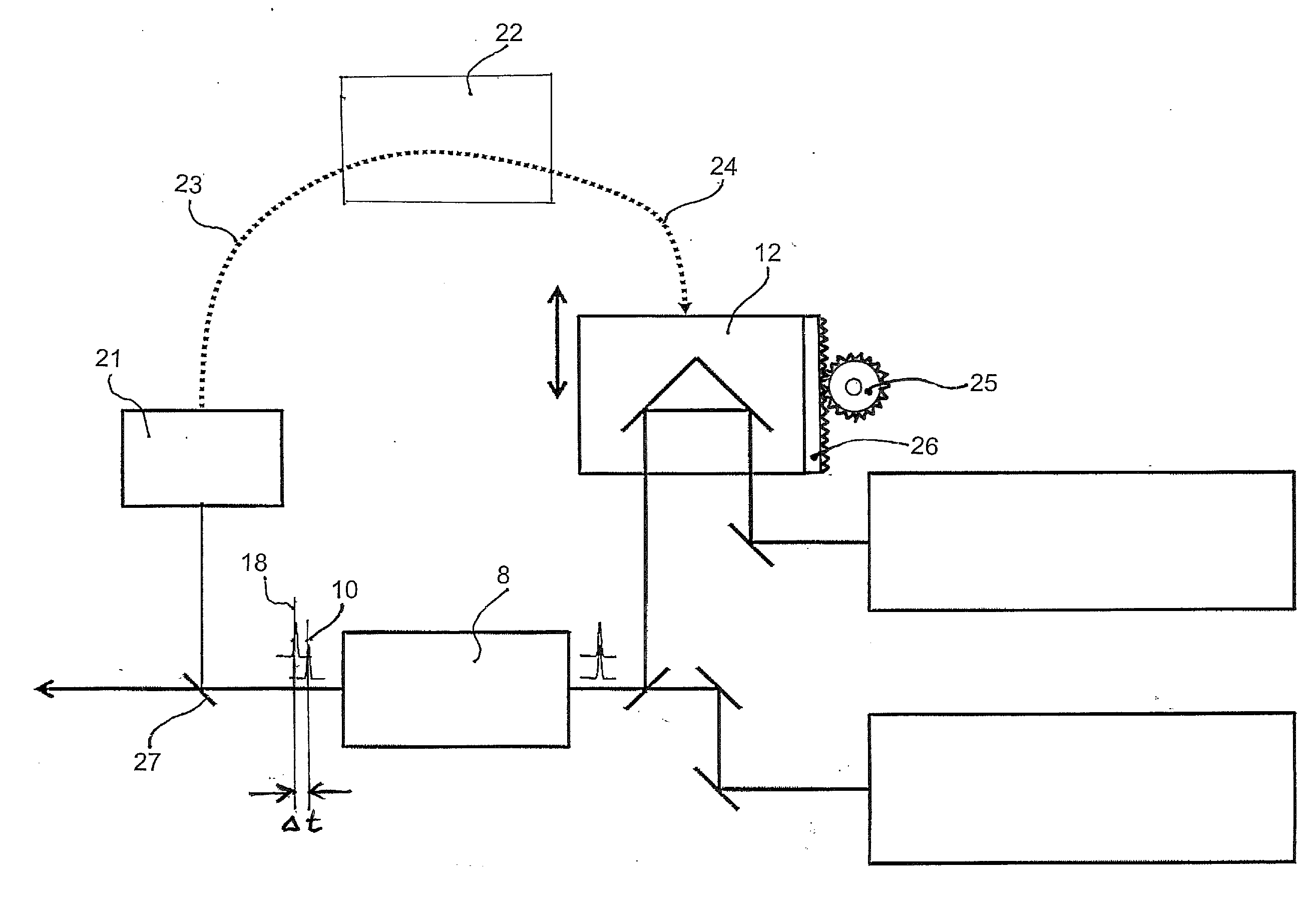
[0011]In addition, the delay stage can be motorized and a control can be provided for controlling the motorized delay stage depending on the time delay detected by a delay detector. This allows even a closed loop control in that a control unit receives a delay signal from the TPA detector, and generates a control signal for moving the delay stage, resulting in a different time delay that is again detected by the TPA detector, resulting again in generating a control signal in the control unit that is fed to the driving mechanism of the delay stage and therefore results in another feedback by measuring the now again adjusted time delay, etc. The control unit may be a simple CPU or a commercially available personal computer PC. While detectors other than TPA detectors are applicable, these TPA detectors have been found to be particularly appropriate for ultrafast laser applications, and are cost-effective and robust, particularly when designed as a LED-based TPA detector.
[0012]The TPA detector can be fed with a picked sample of the laser pulses by a beam splitter provided downstream of the acousto-optic tunable filter that extracts a part of a beam to the delay detector. Preferably, this beam splitter diverts about 5% of an intensity of the first and second laser pulses downstream from the acousto-optic tunable filter to the delay detector, allowing 95% of the intensity to be incident onto the sample for imaging the same. A picked intensity of 5% has turned out to be a sufficient amount for properly detecting the time delay between the laser pulses, while any picked intensity between 1 and 10% would work, i.e. even a lower percentage of the intensity might suffice, while higher intensities can also be tolerated or even useful.
[0013]The first pulsed laser light source includes a first laser and the second pulsed laser light source includes a second laser. Preferably, these laser light sources are designed to emit prechirped laser beams. In the alternative, the first and the second pulsed laser light source may comprise one pump laser combined with an optical parametric oscillator converting the pump laser light into the first and second laser pulses of distinct wavelength. This latter alternative is particularly robust and cost-efficient since it requires only one laser, saving the costs for the second laser and at the same time reducing the risk of failure to only one laser.
Problems solved by technology
Tuning at least one of the wavelengths results in a change of the temporal delay between the pulses and therefore may result in non-optimal imaging if the resulting time delay is non-optimal.
Method used
View moreImage
Smart ImageViewing Examples

Examples
first embodiment
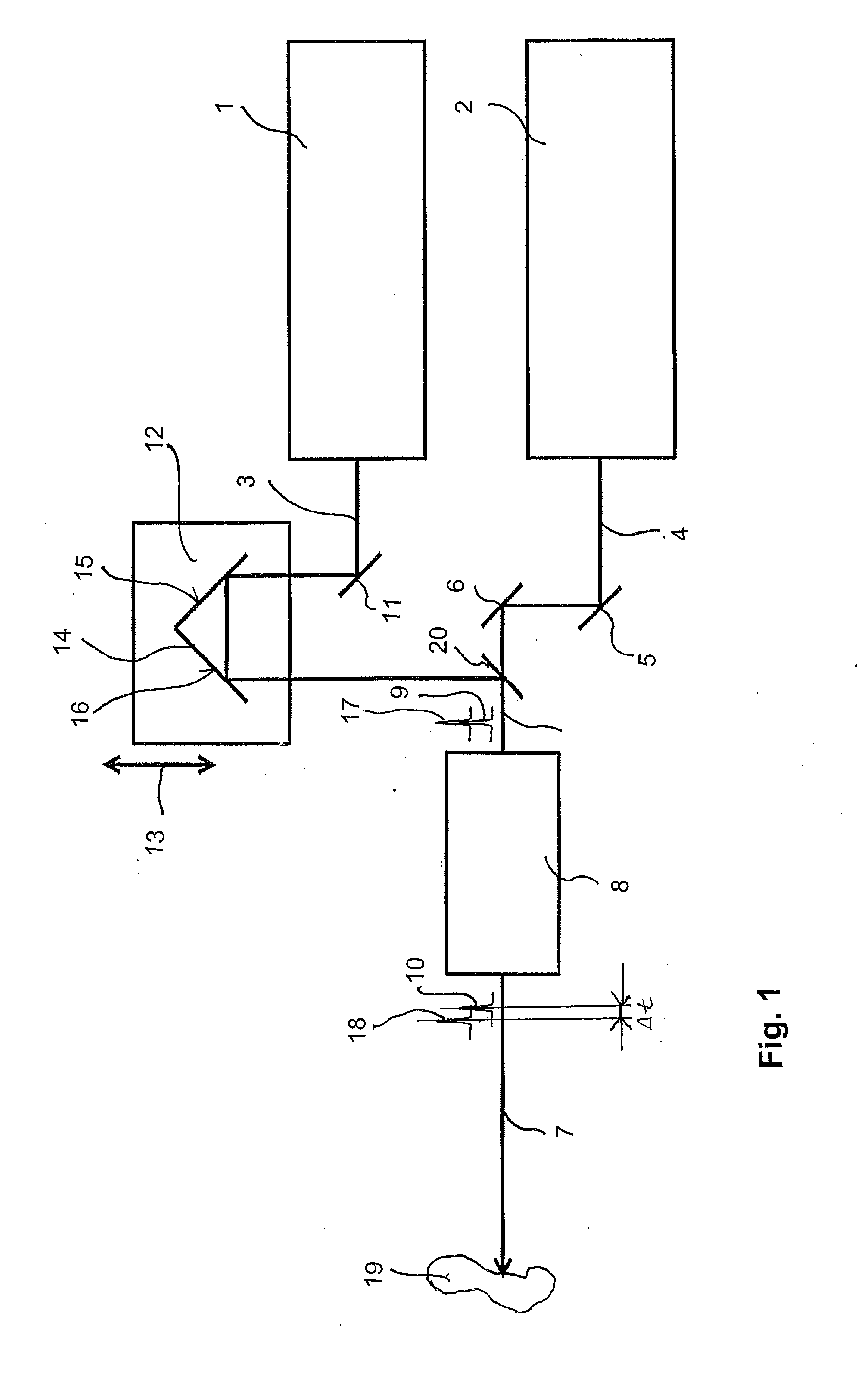
[0016]FIG. 1 shows schematically the invention applying a manual adjustment of the delay stage.
second embodiment
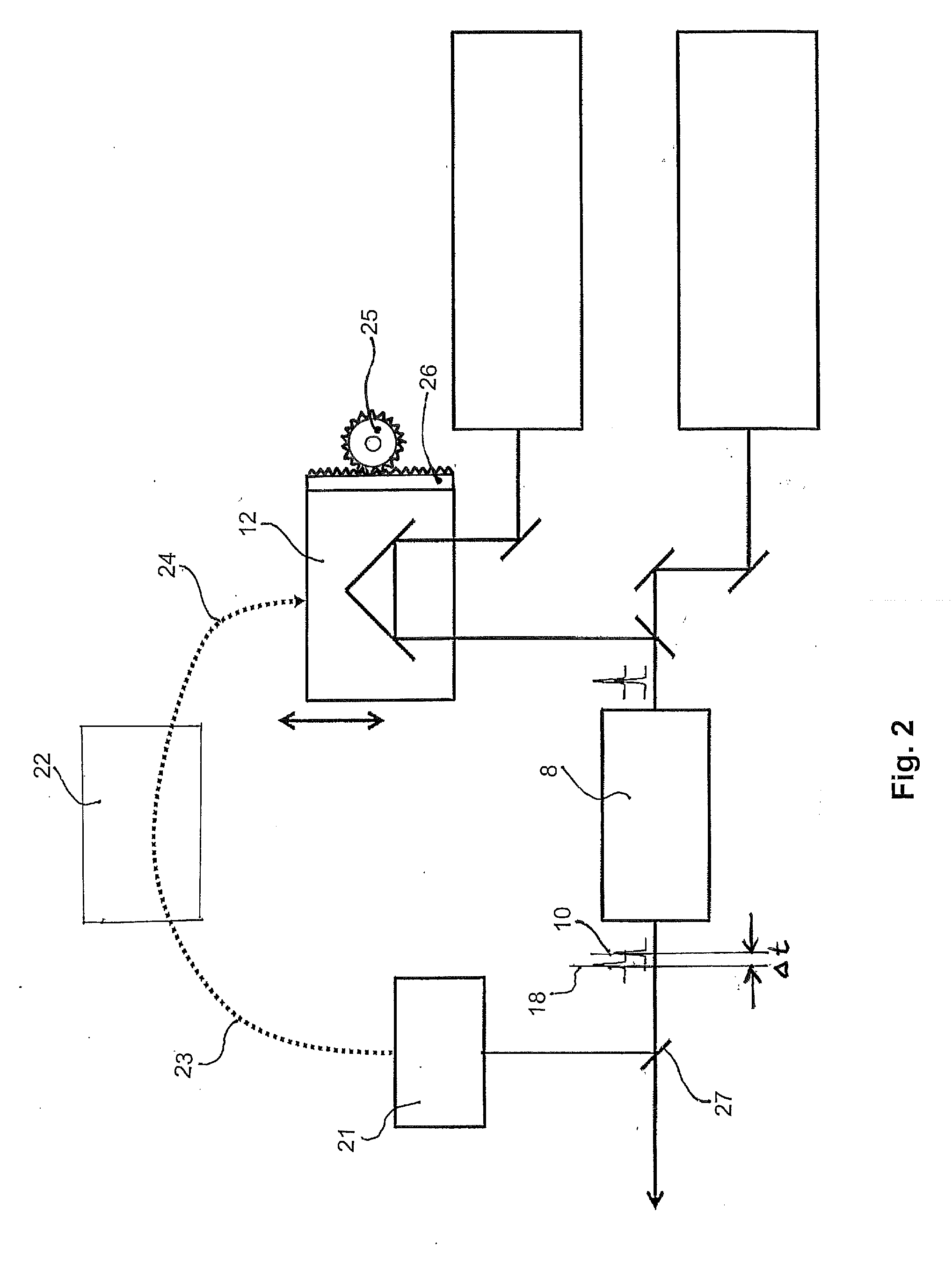
[0017]FIG. 2 shows schematically the invention applying a controlled adjustment of the delay stage.
third embodiment
[0018]FIG. 3 shows schematically the invention applying a controlled adjustment of the delay stage and comprising only one single laser source with two output wavelengths.
Login to View More PUM
 Abstract
A tunable multiple laser pulse scanning microscope and a method of operating the same is described, applying two pulsed laser beams with distinct wavelengths incident on a scanning spot of a sample to be imaged simultaneously or at a specific time delay. The microscope comprises at least two pulsed laser light sources emitting laser light of distinct wavelengths, an acousto-optic tunable filter (AOTF) for tuning at least one of the laser pulses, a delay stage provided upstream of the AOTF, and an actuator for moving delay stage depending on the time delay. As a result, the wavelength of at least one type of pulses is tuned, and the delay between at least two pulses of distinct wavelengths is adjusted.
Description
BACKGROUND OF THE INVENTION[0001]Microscopes applying pulsed laser beams are well-known in the art, particularly, confocal microscopes using two or more pulsed laser beams of distinct wavelengths. The two or more laser pulses are temporarily and spatially synchronized and are of different wavelengths. The laser pulses have to arrive at a particular scanning spot on a sample to be imaged either simultaneously or with a specific time delay between the laser pulses of different wavelengths, depending on the particular type of microscope. Examples for microscopes applying two different laser pulses are for instance a coherent anti-Stokes Raman scattering (CARS) microscope, a stimulated Raman scattering (SRS) microscope, a Raman-induced Kerr-effect scattering (RIKES) microscope, a sum-frequency generation (SFG) microscope, and a stimulated emission depletion (STED) microscope. An example for a microscope applying three distinct wavelengths that are incident on the sample with clearly pre...
Claims
Login to View More Application Information
Patent Timeline
 IPC IPC(8): G02B21/06G02F1/39
CPCG02B21/0076G02B21/0032
InventorKRISHNAMACHARI, VISHNU VARDHANHAY, WILLIAM C.
OwnerLEICA MICROSYSTEMS CMS GMBH