Compact-area capacitive plates for use with spiral inductors having more than one turn

a capacitive plate and capacitive plate technology, applied in the field of electric circuits, can solve the problems of energy loss and complicate to some degree the layout of spiral inductor circuits, and achieve the effect of lessening the interaction with surrounding lossy materials

Active Publication Date: 2011-11-17
HANER RONALD LAMBERT
View PDF9 Cites 77 Cited by
  • Summary
  • Abstract
  • Description
  • Claims
  • Application Information

AI Technical Summary

Benefits of technology

[0017]The capacitive plate 308 in this invention is electrically floating: it is not connected to an electrical ground and is not directly electrically connected (no direct conductive contact) with the corresponding primary spiral inductor 301. The primary spiral inductor 301 and corresponding conductive capacitive plate 308 are electrically insulated from each other. Here, the term “insulated” refers to being electrically insulated in the usual sense: high electrical resistance between structures, thus resisting current.
[0018]Particular embodiments include designing and placing a capacitive plate 308 that is positioned directly underneath the overlying primary inductor 301, resulting in a superposition 311. The shape of this capacitive plate 308 substantially follows the shape of the trace of the overlying primary inductor 301. One intention of this invention is to add capacitance to the primary spiral inductor 301 so that a compact inductance-capacitance structure 311 is achieved. Another intention of this invention is for the designed capacitive plate to serve as a partial RF shield for the primary spiral inductor. This shielding is desired to help reduce or redirect the spiral inductor's E-fields in order to lessen interactions with surrounding lossy materials.

Problems solved by technology

When a spiral inductor is used in an electrical circuit, energy losses occur as a result of interaction of the physical circuit with the spiral inductor's E- and B-fields.
The connective feature of an underpass 105 (or an overpass) is usually necessary for the circuit, and complicates to some degree the layout of spiral inductor circuits.

Method used


Image

  • Compact-area capacitive plates for use with spiral inductors having more than one turn
  • Compact-area capacitive plates for use with spiral inductors having more than one turn
  • Compact-area capacitive plates for use with spiral inductors having more than one turn

Examples


Embodiment Construction

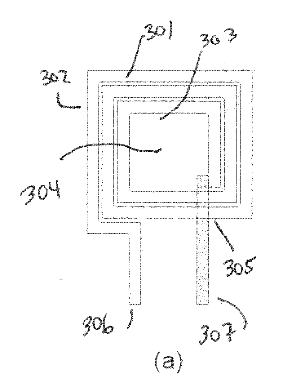
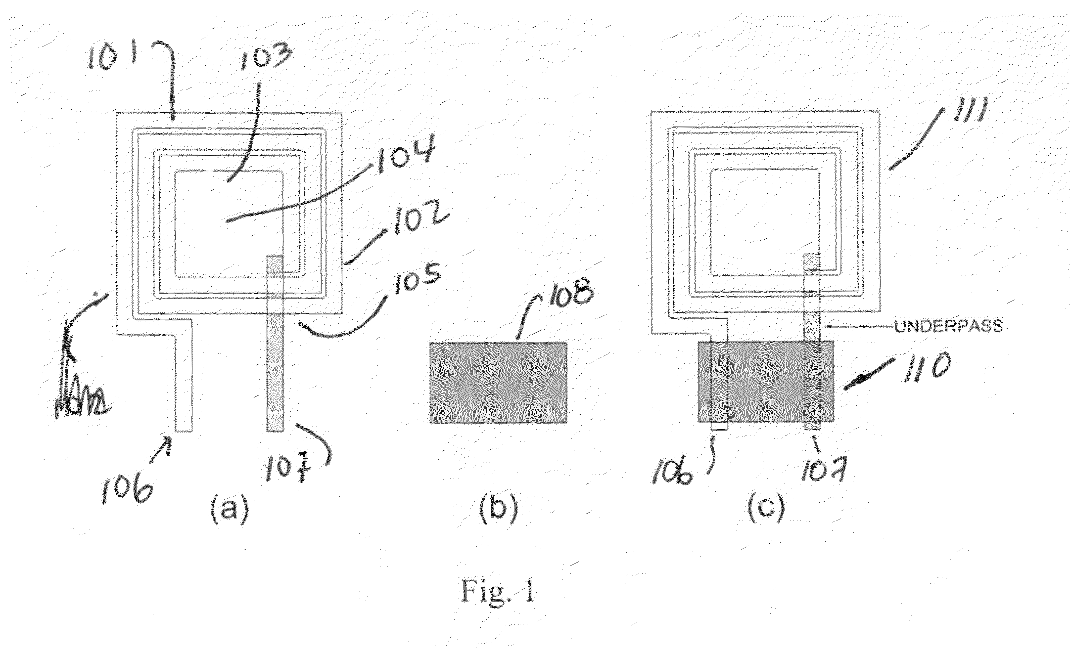
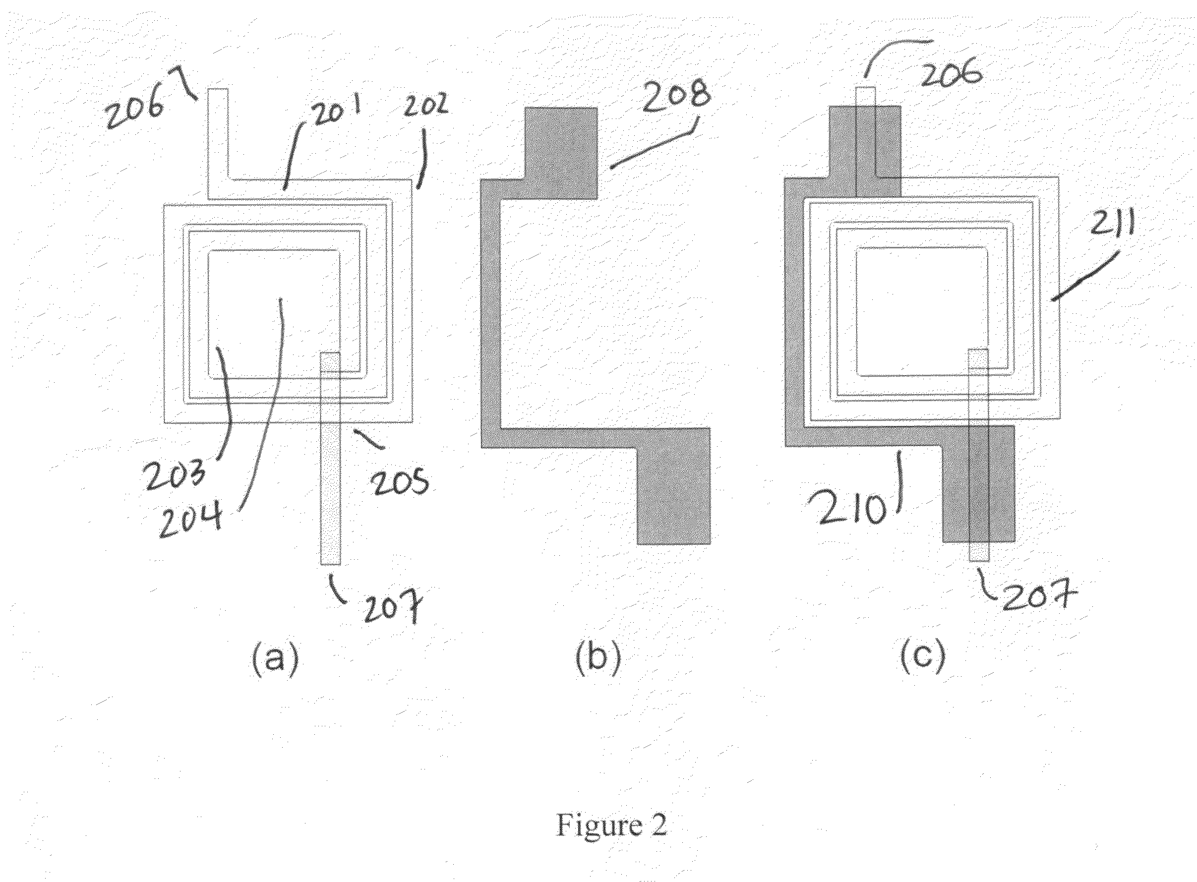
[0050]Presented herein is a method and apparatus for constructing a compact inductive-capacitive LC circuit. This method helps a designer save area when laying out a circuit, without adversely affecting the Q-factor. In some designs, a higher-than-expected Q-factor is realized, compared to Q-factors obtained with conventionally laid-out intermetal plate capacitance or electrically attached discrete capacitive components.

Terminology

[0051]The following terminology used herein is related to the process of producing compact inductive-capacitive LC circuits. Inductive-capacitive LC circuits are also referred to by other terms, including LC circuits, (LC)-tank circuits, RLC circuits, or inductance-capacitance circuits.

[0052]In this specification, the magnetic field is represented by the magnetic flux density, as the capital letter “B.” The electric field is represented by a capital “E.”

[0053]In this specification, the term “primary spiral inductor” refers to the first inductor, i.e., the ...


PUM

PropertyMeasurementUnit
sizesaaaaaaaaaa
thickaaaaaaaaaa
interlayer distancesaaaaaaaaaa

Abstract

A method and an apparatus are described for constructing a compact inductive-capacitive circuit, using a spiral inductor of more than one turn, plus a capacitive plate. This method includes duplicating the layout of the spiral, and then offsetting the duplicate so that the trace pattern of the spiral overlaps its duplicate at an insulating distance away, with the duplicate as an underlying capacitive plate. The plate's trace pattern includes at least one gap, plus an extension of its trace to span the region under the terminals of the spiral inductor. For the case where the spiral inductor has more than one turn—plus an underpass—the capacitive plate may also have more than one turn and may also have an underpass. The resulting pair of underpasses may be either overlapping or nonoverlapping. If overlapping, the full circuit requires at least four metal layers, and at least three if the underpasses are nonoverlapping.

Description

RELATED APPLICATIONS[0001]The present invention claims priority of and is a conversion of U.S. Provisional Patent Application No. 61 / 395,831 filed May 17, 2010 and titled “COMPACT-AREA CAPACITIVE PLATES FOR USE WITH SPIRAL INDUCTORS HAVING MORE THAN ONE TURN.” The contents of such provisional patent application are incorporated herein by reference.FIELD OF THE INVENTION[0002]The field of the invention relates generally to electrical circuits, and more specifically to electrical inductors and inductive-capacitive circuits (LC circuits), also called “(LC)-tank” circuits.BACKGROUND OF THE INVENTION[0003]The invention in concerned with the general style of inductor commonly used on layered supportive media, such as printed circuit boards (PCBs), semiconductor chips, and integrated circuits (ICs). These types of inductors are often referred to as “spiral inductors. Spiral inductors, and resonant circuits containing spiral inductors, are used, for example, in radio frequency and microwave...

Claims


Application Information

Patent Timeline
Patent Type & Authority Applications(United States)
IPC IPC(8): H01P3/08H01F41/00H01P1/20
CPCH01F17/0006Y10T29/4902H01F2017/0046H01F2017/0026H03H7/0115
Inventor HANER, RONALD LAMBERT
Owner HANER RONALD LAMBERT
Why Eureka
Try Eureka