Dc-dc converter circuit

a converter circuit and converter technology, applied in the direction of electric variable regulation, process and machine control, instruments, etc., can solve the problem of surge voltage applied to the rectification element when it is turned off, and achieve the effect of enhancing efficiency

Active Publication Date: 2011-11-17
SANSHA ELECTRIC MFG
View PDF7 Cites 15 Cited by
  • Summary
  • Abstract
  • Description
  • Claims
  • Application Information

AI Technical Summary

Benefits of technology

[0013]Since, according to this invention, the energy which is accumulated in the leakage inductance due to the through current component flowing in the secondary winding when the secondary diode is turned off is regenerated to the load, accordingly no surge voltage is applied to the secondary diode, and moreover the efficiency is enhanced, since there is no heat loss.

Problems solved by technology

However since, when it is turned off, due to accumulated carriers, the secondary diode has a time period trr in which it can conduct current (this time period is termed the reverse recovery time, or the recovery time), accordingly a through current flows in the secondary winding of the transformer during this reverse recovery time, and, due to this, there is the problem that a surge voltage is applied to the rectification element when it has been turned off.

Method used


Image

  • Dc-dc converter circuit
  • Dc-dc converter circuit
  • Dc-dc converter circuit

Examples


Embodiment Construction

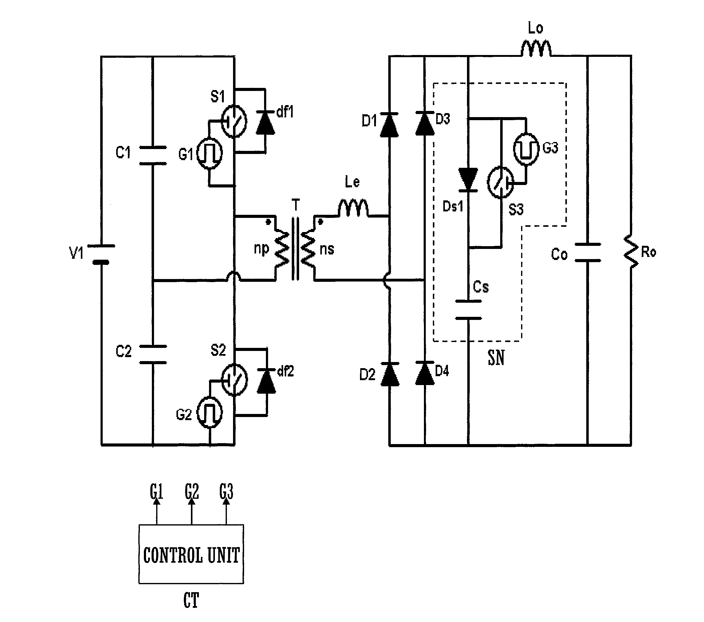
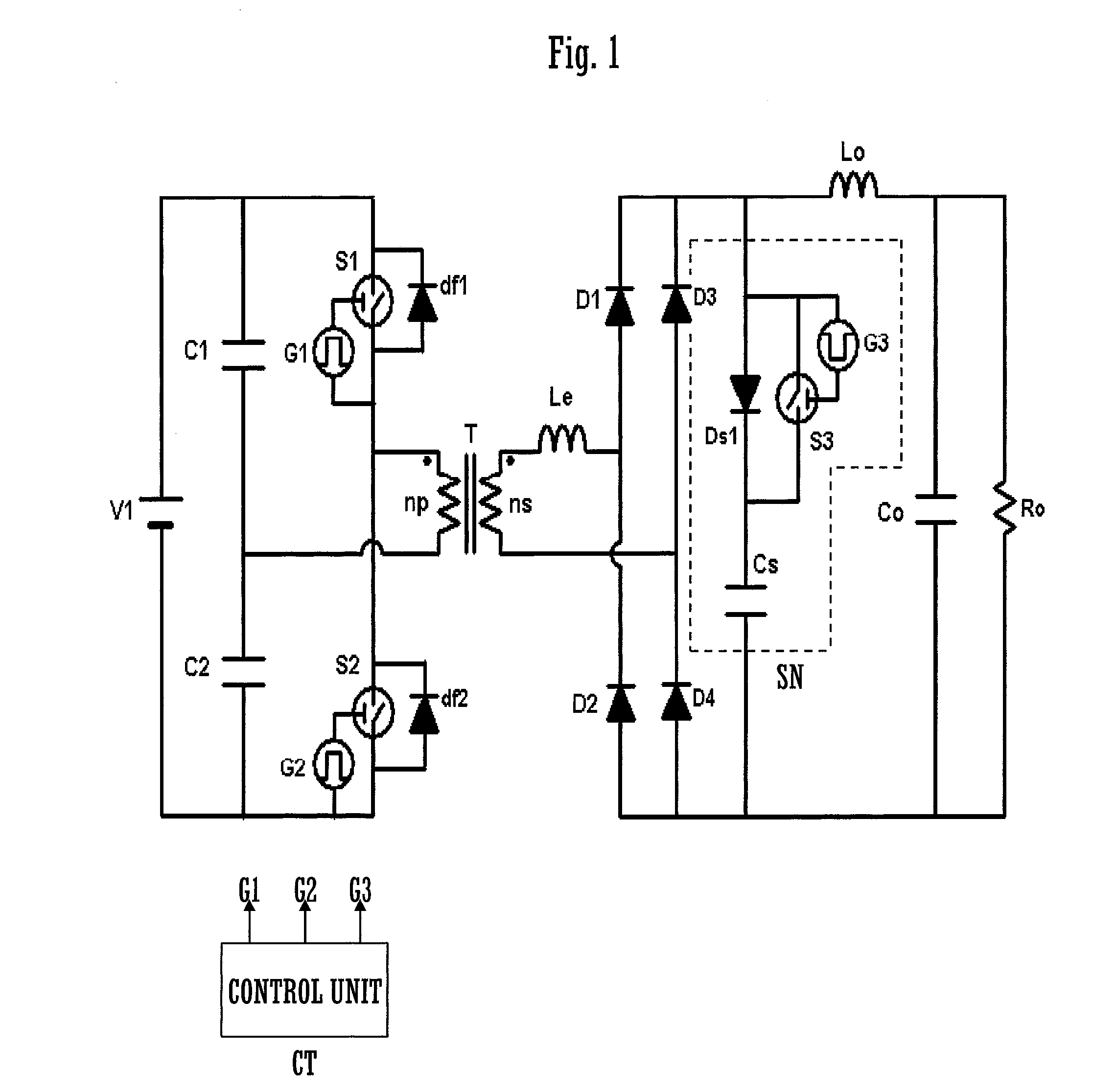
[0019]FIG. 1 is a circuit diagram of a DC-DC converter circuit which is an embodiment of the present invention.

[0020]A series circuit of a first capacitor C1 and a second capacitor C2, which constitutes a voltage source, is connected in parallel with a DC power supply V1, and primary side switching elements, in other words a first switching element S1 and a second switching element S2, are each connected in parallel to these capacitors C1 and C2. Each of these switching elements S1 and S2 is a semiconductor switching element, and may, for example, be an IGBT (insulation gate type bipolar transistor) or a MOS-FET. A primary winding np of a transformer T is connected between the point of connection between the capacitors C1 and C2 and the point of connection between the switching elements S1 and S2. Respective free wheel diodes (clamp diodes) df1 and df2 are connected in reverse parallel to the switching elements S1 and S2. Moreover a control unit CT is provided, which outputs respect...


PUM


Abstract

This DC-DC converter circuit includes a switching circuit which switches a DC power supply with a primary side switching element, a transformer to a primary side winding whereof the output of the switching circuit is applied and which outputs a voltage which has been changed by a predetermined voltage change ratio to a secondary side winding, and secondary diodes for current adjustment connected to the secondary side winding of the transformer. Moreover, it includes a regeneration snubber circuit connected in parallel with the secondary diode circuit and including a series circuit of a discharge blocking diode and a snubber capacitor and a switching element for regeneration connected in parallel with the discharge blocking diode, a filter circuit connected between rectification outputs of the secondary diode circuit, and a control unit which turns the switching element for regeneration ON a predetermined time period after the timing of turning the primary side switching element OFF. The predetermined time period is set to approximately the time period during which the charge, accumulated in the snubber capacitor due to reverse recovery time when one of the secondary diodes has been turned OFF, discharges.

Description

TECHNICAL FIELD[0001]The present invention relates to a DC-DC converter circuit which is provided with a secondary side snubber circuit.BACKGROUND ART[0002]A DC-DC converter circuit is provided with a switching circuit which is a primary side switching element and which switches a DC power supply, with a transformer to whose primary side winding the output of said switching circuit is supplied and which outputs at its secondary side winding a voltage which has been changed by a predetermined voltage change ratio, and a secondary diode for current adjustment which is connected to the secondary side winding of said transformer. Having been rectified by the secondary diode, the output is supplied to a load after being smoothed.[0003]However since, when it is turned off, due to accumulated carriers, the secondary diode has a time period trr in which it can conduct current (this time period is termed the reverse recovery time, or the recovery time), accordingly a through current flows in...

Claims


Application Information

Patent Timeline
Patent Type & Authority Applications(United States)
IPC IPC(8): H02M3/335
CPCH02M1/34Y02B70/1491H02M2001/342H02M3/33569Y02B70/10H02M1/342H02M3/33571
Inventor FUJIYOSHI, TOSHIKAZUKATSUSHIMA, HAJIMEMORIMOTO, KENJIYAMAMURA, SATOSHI
Owner SANSHA ELECTRIC MFG
Why Eureka
Try Eureka