Apparatus and microchip for sorting micro particles

a microchip and apparatus technology, applied in particle and sedimentation analysis, service pipe systems, water mains, etc., can solve the problems of user biohazard, high cost of flow cell and orifice parts, and inability to easily dispose of each of those conventional flow cytometries (cell sorters) by users, so as to eliminate cross contamination

Active Publication Date: 2011-11-24
SONY CORP
View PDF7 Cites 49 Cited by
  • Summary
  • Abstract
  • Description
  • Claims
  • Application Information

AI Technical Summary

Benefits of technology

[0025]According to the present invention, it is possible to provide the micro-particle sorting apparatus capable of performing the high-speed analysis and the safe, high-speed, inexpensive sorting by e

Problems solved by technology

Each of those conventional flow cytometries (cell sorters) cannot be easily disposed of by a user because the flow cell part constituting the flow path system is made of expensive quartz and is constituted of the orifice part separate from the flow cell.
Thus, even if the flow cell part and the orifice part are sufficiently washed in every measurement, there is a fear that cross contamination of samples between measurements occur.
Further, the space constituting the sorting system is set as an open space or a space having low air tightness, and hence contamination materials such as micro liquid drops (aerosol) generating during formation of the liquid drops may be mixed into a sample at the time of measurement, or biohazard such as infection or exposure with respect to apparatus users due to the ae

Method used


Image

  • Apparatus and microchip for sorting micro particles
  • Apparatus and microchip for sorting micro particles
  • Apparatus and microchip for sorting micro particles

Examples


Embodiment Construction

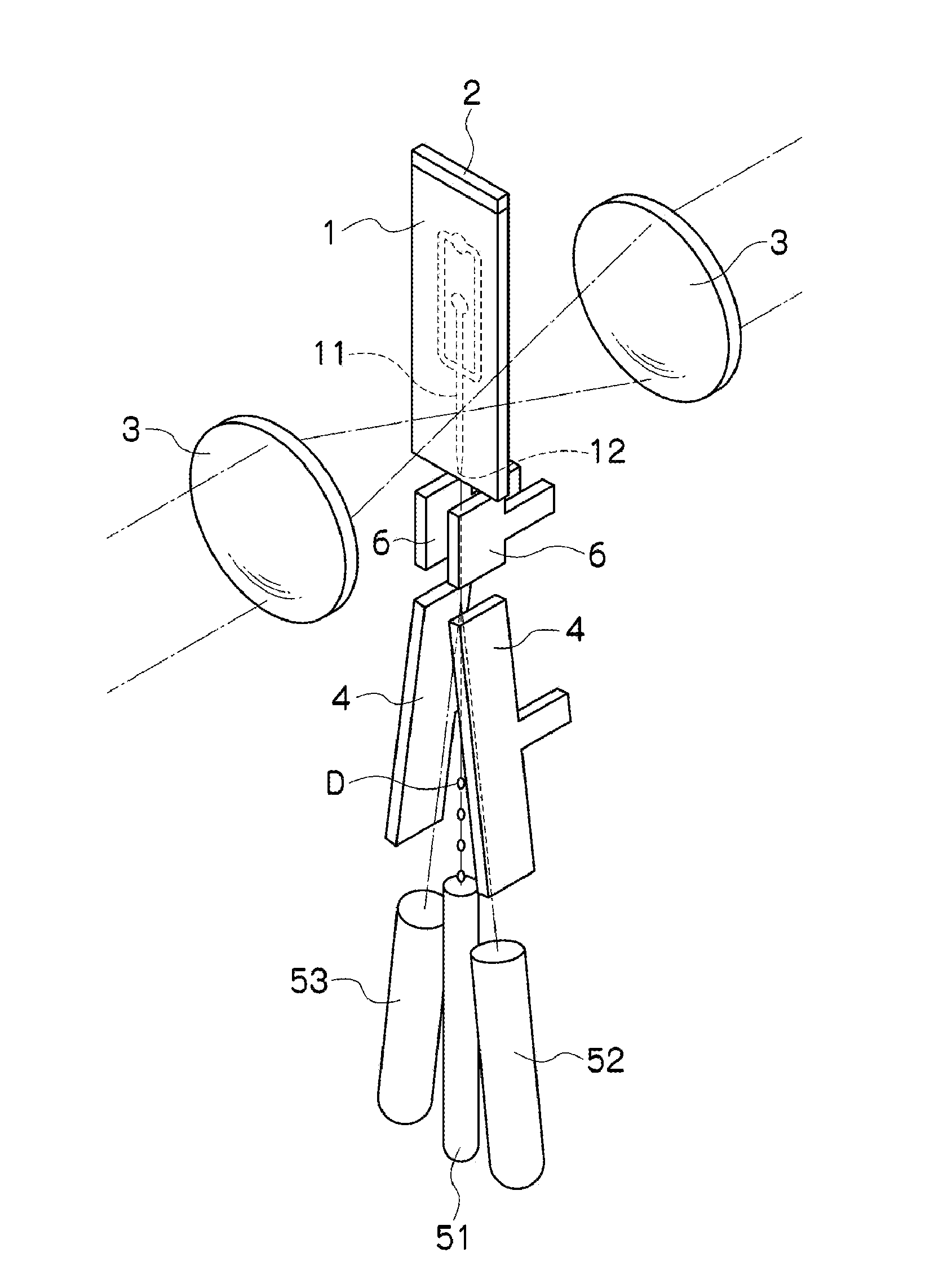
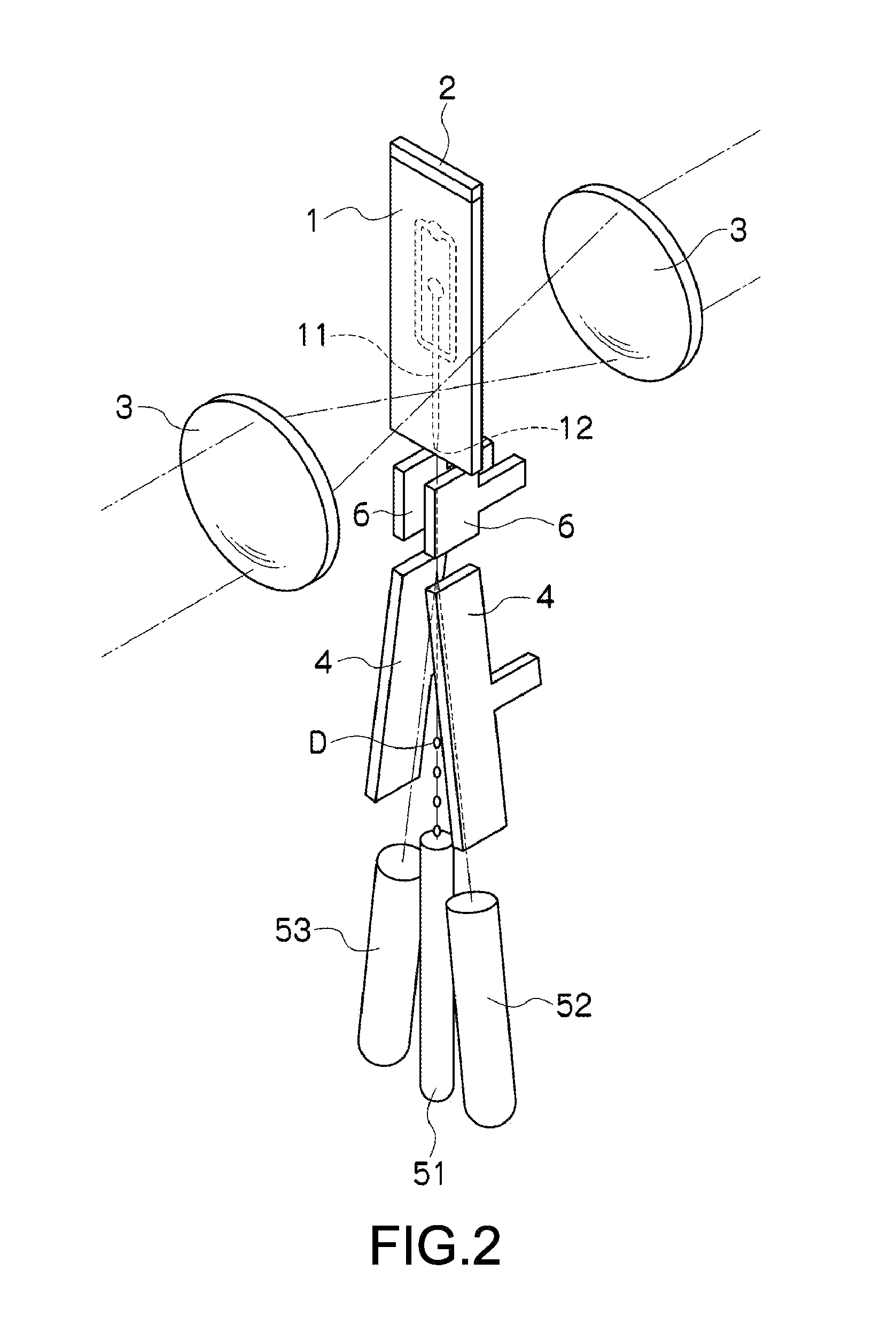
[0039]Hereinafter, a preferred mode for carrying out the invention will be described with reference to the drawings. It should be noted that an embodiment to be described below shows one example of a typical embodiment of the present invention, and shall not be construed to limit the scope of the present invention. It should be noted that the description will be made in the following order.[0040]1. Micro-particle sorting apparatus[0041]2. Microchip[0042](1) Flow path[0043](2) Micro tube and limiter portion[0044](3) Light-irradiated portion[0045](4) Pressure-rising portion and orifice[0046]3. Oscillating element[0047]4. Width and Depth of flow path at each location of microchip[0048]5. Operation of micro-particle sorting apparatus[0049]6. Cartridge

1. Micro-Particle Sorting Apparatus

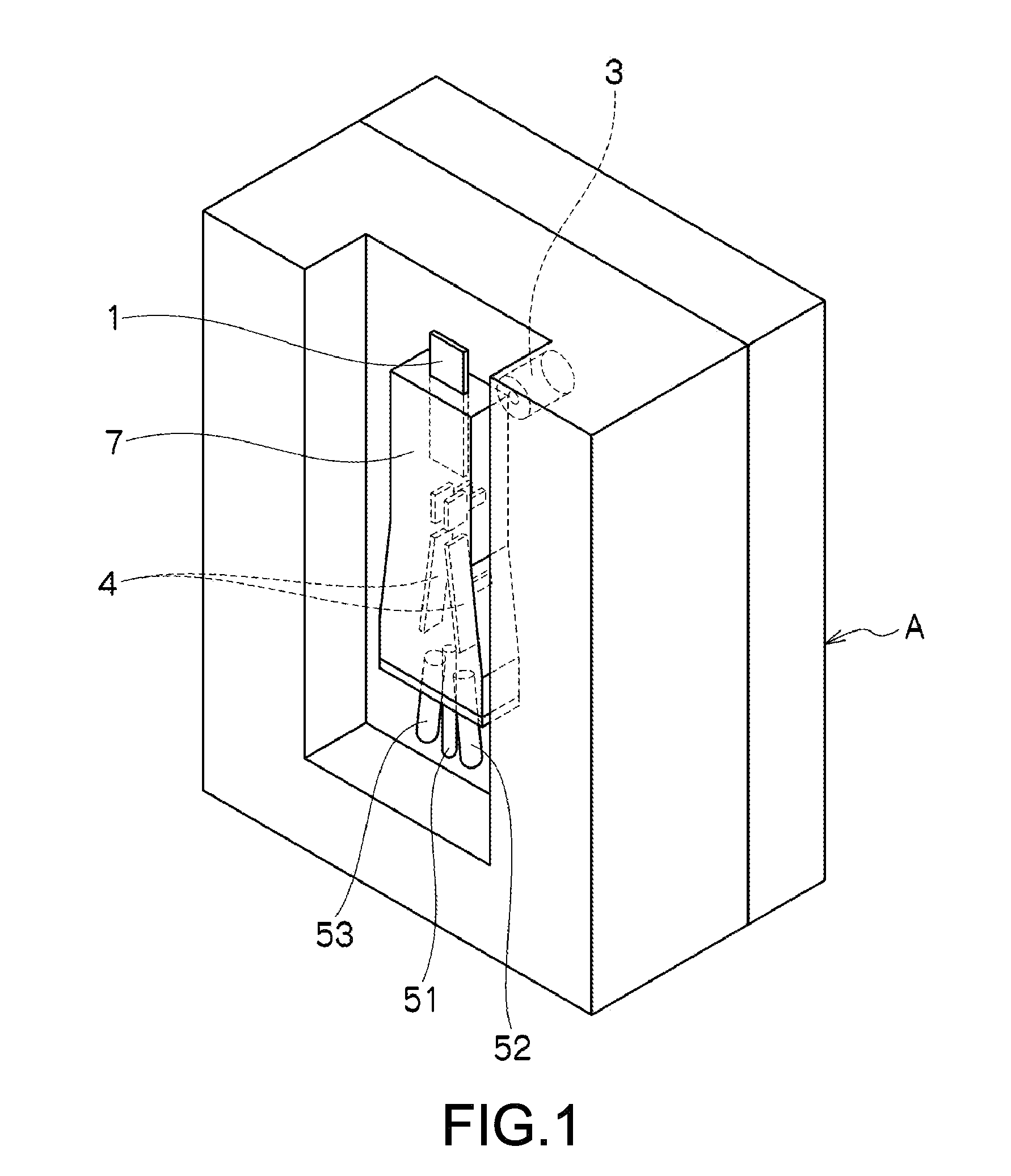
[0050]FIG. 1 is a view showing a schematic configuration of a micro-particle sorting apparatus according to the present invention. In the drawing, the micro-particle sorting apparatus denoted by the symbol...


PUM


Abstract

In one example embodiment, a micro-particle sorting apparatus includes: (a) a microchip in which a flow path through which liquid containing a micro particle flows and an orifice through which the liquid flowing through the flow path is discharged into a space outside the chip; (b) an oscillating element for transforming the liquid into a liquid drop and discharging the liquid drop at the orifice; (c) a charge means for adding an electric charge to the discharged liquid drop; (d) an optical detection means that detects an optical property of the micro particle flowing through the flow path, upstream of a liquid-delivering direction with respect to the orifice; (e) paired electrodes opposed to each other while sandwiching the moving liquid drop along a movement direction of the liquid drop discharged into the space outside the chip; and two containers that collect the liquid drop passing between the paired electrodes.

Description

TECHNICAL FIELD [0001]The present invention relates to an apparatus and a microchip for sorting micro particles. More specifically, the present invention relates to a micro-particle sorting apparatus and the like, that detects properties of micro particles, which flow through a flow path formed in a microchip, within the chip, discharges liquid drops containing the micro particles to the outside of the chip, and controls the movement directions of the liquid drops on the basis of the detected properties of the micro particles for sorting.BACKGROUND ART[0002]Conventionally, in order to identify properties of micro particles such as biologically-relevant micro particles such as cells, microorganisms, liposomes or synthetic particles such as latex particles, gel particles, or industrial particles, there has been utilized an apparatus that introduces dispersion liquid of the micro particles into the flow path, and optically measures the properties of the micro particles that have been i...

Claims


Application Information

Patent Timeline
IPC IPC(8): G01N15/14F15D1/00G01N27/447
CPCB01L3/0268B01L3/502746B01L3/502761B01L3/502776B01L2400/0433B01L2400/0487G01N2015/149G01N15/1484G01N2015/1488G01N15/1404G01N27/44791G01N2015/1422G01N2015/1481G01N15/1459G01N2015/1006Y10T137/8158G01N15/1434G01N2015/1409G01N27/44743G01N2015/1081
Inventor SHINODA, MASATAKA
Owner SONY CORP
Why Eureka
Try Eureka