Exhaust gas heat recovery heat exchanger

Inactive Publication Date: 2011-12-01
DELPHI TECH INC
View PDF6 Cites 34 Cited by
  • Summary
  • Abstract
  • Description
  • Claims
  • Application Information

AI Technical Summary

Benefits of technology

[0007]The coiled tubes may be formed of a fluid tube having a non-circular cross-sectional area with at least one edge extending along a local axis. The fluid tube may be twisted about a local axis defining a twisted fluid passageway. A bypass control valve may be disposed in the internal passageway to bypass hot exhaust gas flow from the internal passageway to the annular passageway to control and

Problems solved by technology

With the advent of greater efficiency internal combustion engines and hybrid vehicles having smaller internal combustion engi

Method used


Image

  • Exhaust gas heat recovery heat exchanger
  • Exhaust gas heat recovery heat exchanger
  • Exhaust gas heat recovery heat exchanger

Examples


Embodiment Construction

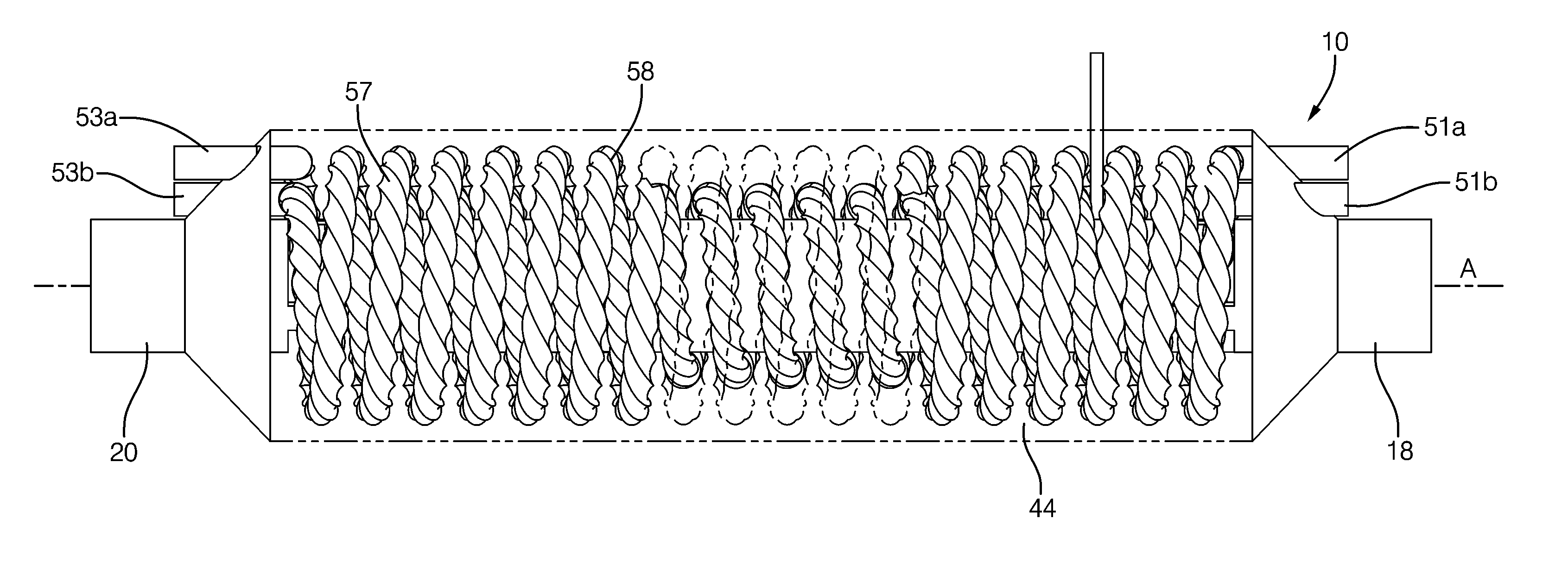
[0018]Shown in FIGS. 1 through 6, wherein like numerals indicate corresponding parts throughout the several views, is an embodiment of an exhaust gas heat recovery (EGHR) heat exchanger 10 of the present invention. The EGHR heat exchanger 10 may be used for recovering waste heat from the exhaust gas of an internal combustion engine of a motor vehicle to provide supplementary heat to the passenger compartment as well as to heat automotive fluids, such as the windshield wiper fluid, engine oil, and transmission fluids. For hybrid vehicles, the waste heat from the internal combustion engine may also be recovered to provide heat to the battery compartment to extend the range of the battery life in cold operating conditions.

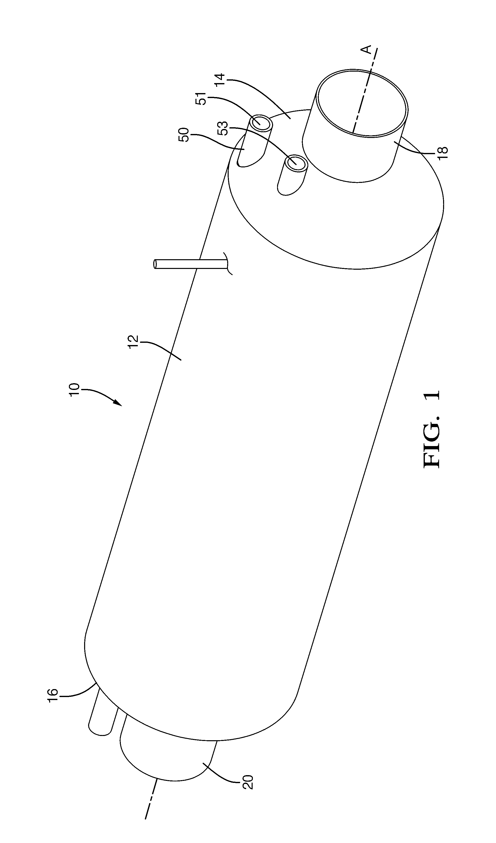
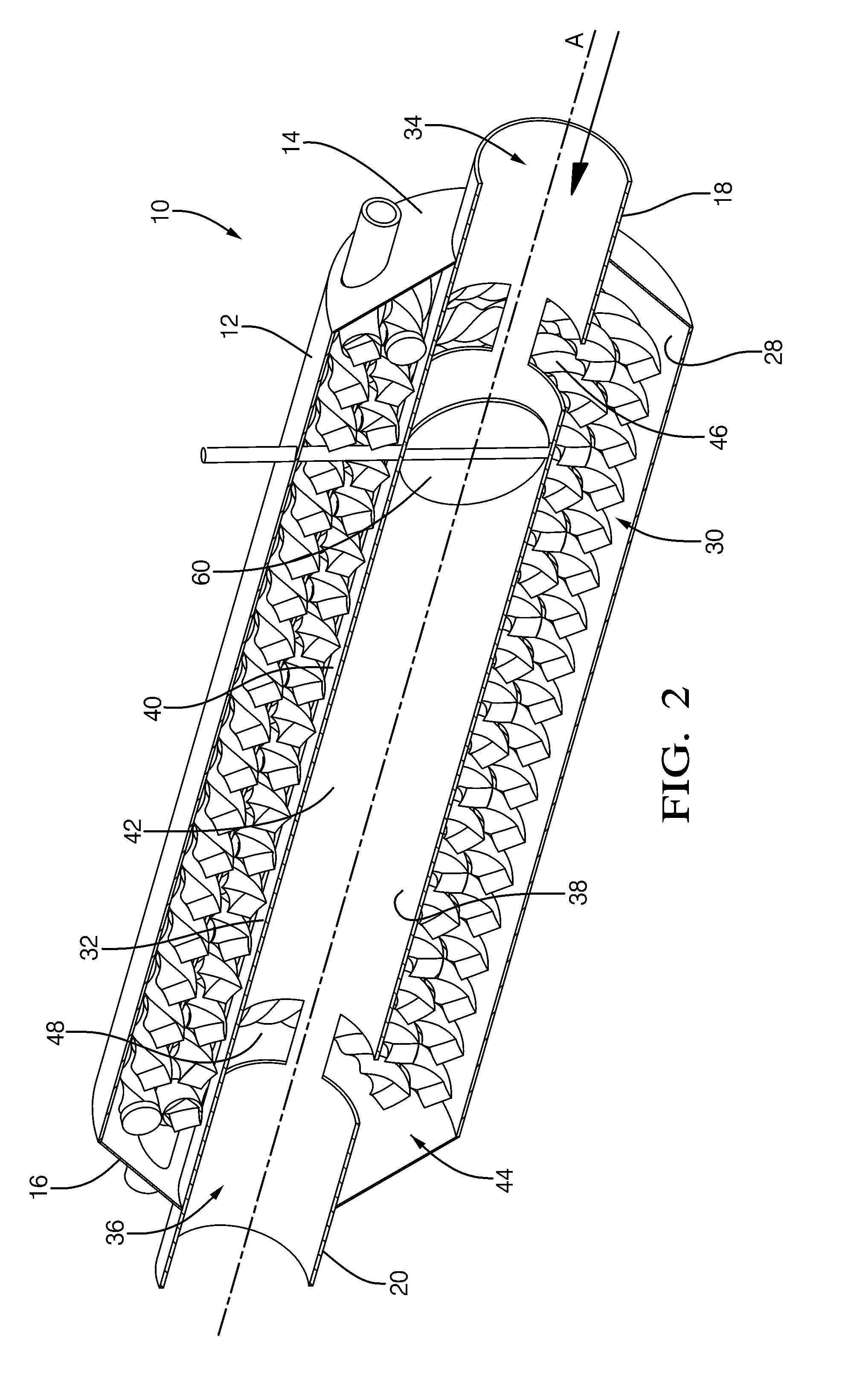
[0019]Shown in FIG. 1 is a perspective view of the EGHR heat exchanger 10. The EGHR heat exchanger 10 includes an elongated housing 12 extending along a longitudinal axis A. The elongated housing 12 includes a first end cap 14 and a second end cap 16 axially spaced fr...


PUM


Abstract

An exhaust gas heat recovery (EGHR) heat exchanger for an internal combustion engine having a housing, a cylindrical body disposed within the housing, an annular exhaust gas passageway, and a central exhaust gas passageway. The EGHR heat exchanger also includes a bypass valve disposed within the central passageway and adapted to selectively by-pass a portion of the exhaust gas from the central exhaust gas passageway to the annular passageway, and at least one twisted tube having at least one edge coiled within the annular exhaust gas passageway.

Description

CROSS-REFERENCE TO RELATED APPLICATION[0001]This application claims the benefit of U.S. Provisional Patent Application Ser. No. 61 / 350,157 for an EXHAUST GAS HEAT RECOVERY EXCHANGER, filed on Jun. 1, 2010, which is hereby incorporated by reference in its entirety.TECHNICAL FIELD OF INVENTION[0002]The present disclosure relates to a heat exchanger for a motor vehicle; more particularly, to a heat exchanger for recovering heat from the exhaust of an internal combustion engine of the motor vehicle.BACKGROUND OF INVENTION[0003]A heater core, which is located inside a heating, ventilating, and air conditioning (HVAC) module of a motor vehicle supplies thermal energy to the passenger compartment for comfort heating. The heater core is typically a liquid-to-air heat exchanger, in which the liquid is hot coolant from an internal combustion engine. With the advent of greater efficiency internal combustion engines and hybrid vehicles having smaller internal combustion engines, the amount of t...

Claims


Application Information

Patent Timeline
IPC IPC(8): F01N5/02C09K5/10B60H1/00
CPCF01N3/043F01N5/02F28D7/0083F28D7/024Y02T10/20F28F1/08F28F27/02F28F2250/06Y02T10/16F28F1/04Y02T10/12
Inventor ACRE, JAMES A.BRIGHT, JAMES A.KOO, JAMES J.ZIMA, MARK J.
Owner DELPHI TECH INC
Why Eureka
Try Eureka