
Method for preventing crack formation and for slowing down the advancement of a crack in metal aircraft structures by means of laser shock rays

a technology of laser shock rays and cracks, which is applied in the direction of aircraft maintenance, manufacturing tools, transportation and packaging, etc., can solve the problem of as little roughening of the surface, and achieve the effect of avoiding accidental irradiation of the damaged area itsel

Active Publication Date: 2011-12-01
AIRBUS OPERATIONS GMBH
View PDF17 Cites 11 Cited by
  • Summary
  • Abstract
  • Description
  • Claims
  • Application Information

AI Technical Summary

Benefits of technology

The present invention provides a method for preventing crack formation and slowing down the advancement of cracks in metal aircraft structures by using laser shock irradiation. The method allows for the treatment of damaged areas with minimal weakening of the surrounding areas. The method can be used during the manufacture of the aircraft and can increase fatigue strength, reduce operating costs, and improve safety. The method uses laser beams to create compressive residual stresses in the material, which prevents cracks from forming and spreading. The first superficial region around the damaged area is treated with a first laser beam, and a second superficial region close to the first region is treated with a second laser beam of a different wavelength and pulse frequency to adjust the type and depth of the compressive residual stresses.

Problems solved by technology

Furthermore, the surface is to be roughened as little as possible by the method.

Method used


Image

  • Method for preventing crack formation and for slowing down the advancement of a crack in metal aircraft structures by means of laser shock rays
  • Method for preventing crack formation and for slowing down the advancement of a crack in metal aircraft structures by means of laser shock rays
  • Method for preventing crack formation and for slowing down the advancement of a crack in metal aircraft structures by means of laser shock rays

Examples


first embodiment

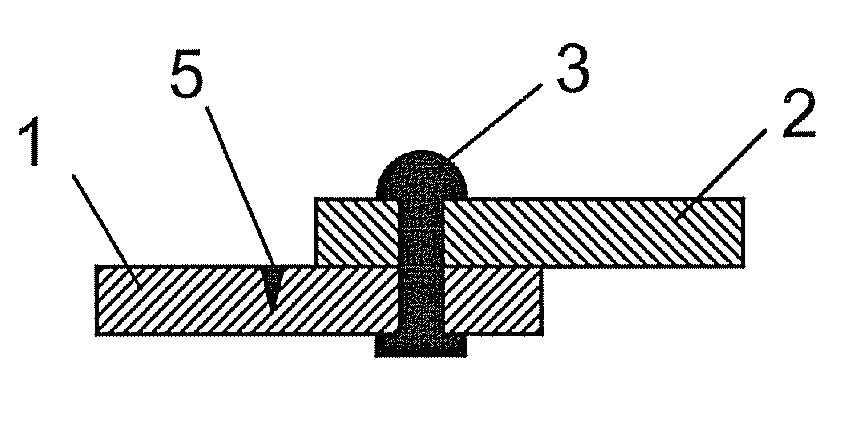
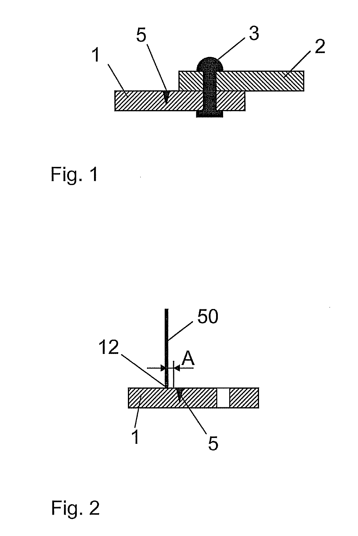
[0032]FIG. 2 is a schematic sectional view of a laser shock irradiation of an aircraft structural part 1 according to a Here, the aircraft structural part 1 is shown without the second aircraft structural part 2 and without the rivet connections 3. The damaged area 5 extends into the image plane. A first laser beam 50 is directed onto the aircraft structural part 1. The laser beam 50 impacts the aircraft structural part 1 at a point of impact 12. In this stage of the method, the point of impact 12 is at a distance A from the damaged area 5. In the figure, the distance A is indicated by a vertical aid line and two arrows.

second embodiment

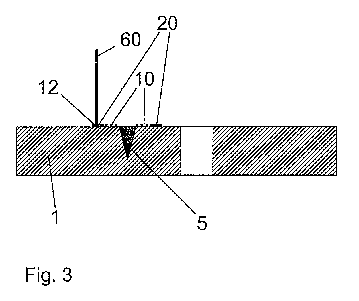
[0033]FIG. 3 is a schematic sectional view of a laser shock irradiation of an aircraft structural part 1 according to a Provided next to the damaged area 5 are a first superficial region 10 and a second superficial region 20 of the aircraft structural part 1 for a laser shock beam treatment. In the illustrated stage of the method, a second laser beam60 is directed at the second superficial region 20 at a point of impact 12. The laser is moved in a continuous path over the second superficial region 20 and performs a laser shock irradiation. In this preferred embodiment, the laser shock irradiation of the second superficial region 20 is performed in addition to the laser shock irradiation of the first superficial region 10. While the first superficial region was subjected to laser shock irradiation by the first laser beam 50, a second laser beam 60 is used for the second superficial region. In this embodiment, the second laser beam 60 has different characteristics compared to the fir...


PUM

PropertyMeasurementUnit
distanceaaaaaaaaaa
distanceaaaaaaaaaa
compressive prestressaaaaaaaaaa

Abstract

The present invention provides a method for preventing the forming of cracks and slowing the crack propagation in metallic airplane structural parts by laser shock peening with the following steps: Providing an airplane structural part having a crack; irradiating a first surface area of the airplane structural part close to the crack with a first pulsed laser beam having a first wavelength and a first pulsation frequency, wherein energy of the first laser beam is absorbed by the airplane structural part and a shock wave runs through the airplane structural part, which creates compressive prestressings in the airplane structural part.

Description

CROSS-REFERENCE TO RELATED APPLICATIONS[0001]This application is a continuation of and claims priority to PCT International Application No. PCT / EP2009 / 065931 filed Nov. 26, 2009, which claims the benefit of and priority to U.S. Provisional Application No. 61 / 120,158, filed Dec. 5, 2008 and German Patent Application No. 10 2008 044 407.3, filed Dec. 5, 2008, the entire disclosures of which are herein incorporated by reference.FIELD OF THE INVENTION[0002]The present invention relates to a method for preventing crack formation and for slowing down the advancement of a crack in metal aircraft structures.[0003]Cracks in aircraft structures are usually attributed to a weakening of material due to static or dynamic mechanical stresses. In particular, material fatigue results from vibration stresses. Cracks are regarded as serious damage to the aircraft structure and require immediate repair measures. The mentioned cracks are the result of normal flight operation.[0004]In addition, the form...

Claims


Application Information

Patent Timeline
Patent Type & Authority Applications(United States)
IPC IPC(8): B23K26/00B23K26/352
CPCB64F5/0081C21D10/005C21D10/00B64F5/40
Inventor STEINWANDEL, JUERGENFURFARI, DOMENICOOHRLOFF, NIKOLAUSDALLE DONNE, CLAUDIO
Owner AIRBUS OPERATIONS GMBH
Learn More