Laser-based methods and systems for corneal surgery

a laser-based, corneal technology, applied in the field of laser-based methods and systems for corneal surgery, can solve the problems of poor predictability of surgery, lack of reproducibility, and deemed unsuitable for eye surgery, and achieve the effect of minimising the risk of eye damag

Inactive Publication Date: 2011-12-01
PEYMAN GHOLAM A
View PDF0 Cites 13 Cited by
  • Summary
  • Abstract
  • Description
  • Claims
  • Application Information

AI Technical Summary

Benefits of technology

[0031]The present invention is directed to methods and systems for cornea tissue ablation, wherein the delivery head of the laser source is positioned a spaced distance from the

Problems solved by technology

As is well known in the art, there are, however, several significant drawbacks and disadvantages associated with mechanical surgical methods.
Among the disadvantages are the lack of reproducibility and, hence, poor predictability of surgical results.
CO2 laser and CO:MgF2 lasers are thus often deemed ill-suited for eye surgery.
This etch depth could, and in all likelihood would, result in an unacceptable level of eye damage.
It has, however, been reported that at such a peak power level tissue molecules can, and in most instances will, be “pulled” apart under the strong electric field of the transmitted laser energy (or light), which causes dielectric breakdown of the material.
The reaction is typically very violent, and the effects are widely variable.
Further, the amount of tissue removed is a highly non-linear function of the incident beam power.
Thus, the tissue removal rate is difficult to control.
Additionally, accidental exposure of the endothelium by the laser beam is a constant concern.
The no

Method used


Image

  • Laser-based methods and systems for corneal surgery
  • Laser-based methods and systems for corneal surgery
  • Laser-based methods and systems for corneal surgery

Examples


example 1

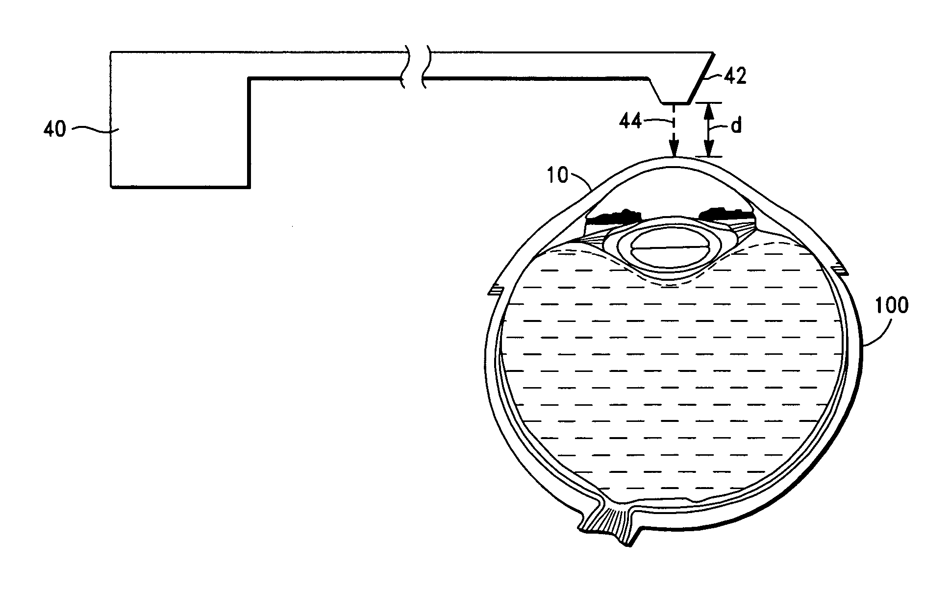
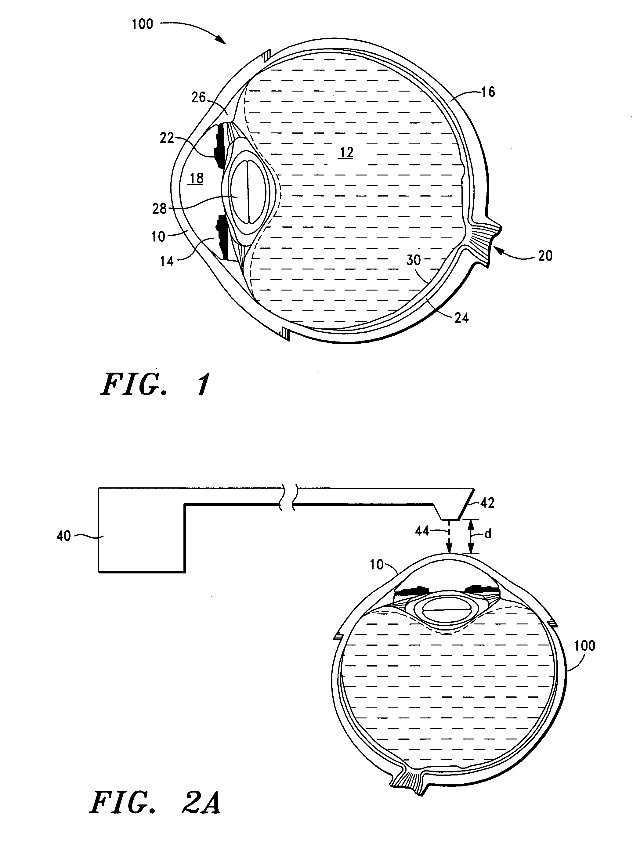
[0123]Referring to FIGS. 3 and 4, the laser delivery head 42 is initially positioned a spaced distance (d) in the range of approximately 1.0-5.0 cm over the patient's cornea 10 via the laser source control means.

[0124]The size, degree and position of the laser beam 44 is selected and controlled by the laser source control means. The desired laser beam pattern, e.g. circular, scattered, linear, etc. is also selected and controlled by the laser source control means.

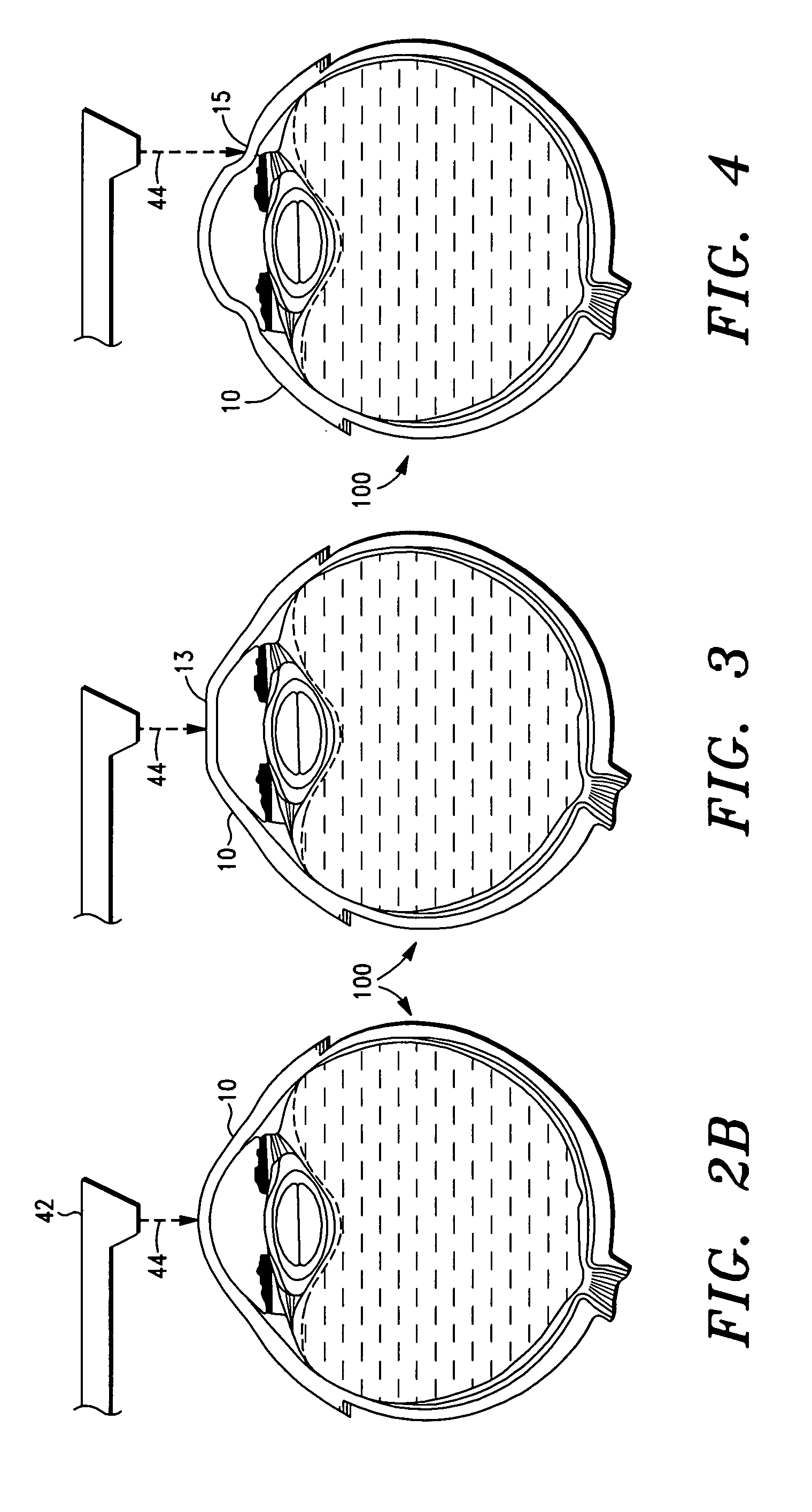
[0125]The noted laser beam 44 is then directed toward the eye 100 to a target eye structure, in this example, the cornea 10 via the laser head 42 (and appropriate optics and prisms) to perform myopic correction. FIG. 3 illustrates the ablation of the cornea 10, wherein a center portion 13 is flattened via the surface ablation of the cornea 10, during the myopic correction procedure.

example 2

[0126]In this example, the laser delivery head 42 is similarly positioned a spaced distance (d) in the range of approximately 5-10 cm over the patient's cornea 10 via the laser source control means. The laser beam 44 is then directed to the cornea 10 via the laser head 42 to perform hyperopia correction. FIG. 4 illustrates the surface ablation of the peripheral cornea 15 during the hyperopia correction procedure.

example 3

[0127]In this example, the laser delivery head 42 is similarly initially positioned a spaced distance (d) in the range of approximately 1.0-20 mm over the patient's cornea 10 via the laser source control means. The laser beam 44 is then directed to the cornea 10 via the laser head 42 to perform a LASIK® procedure, i.e. correction of a refractive error, by initially forming a corneal flap 17 and then, as illustrated in FIG. 5, performing surface ablation of the cornea 10 under the corneal flap 17.


PUM


Abstract

A method for surface ablation of cornea tissue comprising the steps of (i) providing a laser source that is adapted to generate and transmit focused pulsed laser energy, the laser source including a delivery head that is adapted to direct the laser energy to a target structure of an eye, (ii) disposing the delivery head a spaced distance from the target eye structure, and (iii) transmitting the laser energy to the target eye structure, whereby the surface of the eye structure tissue is primarily, more preferably, solely ablated.

Description

FIELD OF THE INVENTION[0001]The present invention relates to systems and methods for corneal and intraocular surgery. More particularly, the present invention relates to laser-based methods and systems for performing surface ablation of cornea tissue.BACKGROUND OF THE INVENTION[0002]Various surgical procedures have been developed and employed to correct refractive defects (or errors) and / or treat eye diseases. Mechanical methods were initially employed to correct refractive defects by changing the curvature of the eye. These mechanical methods involve removal of a thin layer of tissue from the cornea by a microkeratome, freezing the tissue at the temperature of liquid nitrogen, and re-shaping the tissue in a specially designed lathe. The thin layer of tissue is then re-attached to the eye by suture.[0003]As is well known in the art, there are, however, several significant drawbacks and disadvantages associated with mechanical surgical methods. Among the disadvantages are the lack of...

Claims


Application Information

Patent Timeline
IPC IPC(8): A61F9/01
CPCA61F2009/00872A61F9/00827
Inventor PEYMAN, GHOLAM A.
Owner PEYMAN GHOLAM A
Why Eureka
Try Eureka