Optical member, and organic electroluminescence display device provided with the optical member

Inactive Publication Date: 2011-12-08
UDC IRELAND
View PDF4 Cites 42 Cited by
  • Summary
  • Abstract
  • Description
  • Claims
  • Application Information

AI Technical Summary

Benefits of technology

[0030]According to the present invention, it is possible to solve the above conventional problems, to achieve the above objects, and to provide an optical member capable of improving light extraction efficiency of an organic electroluminescence display device and reducing image blurring, and an organic electroluminescence display device provided with the optical member.
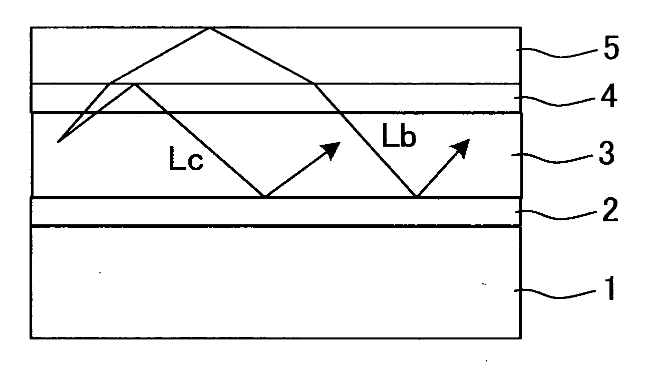
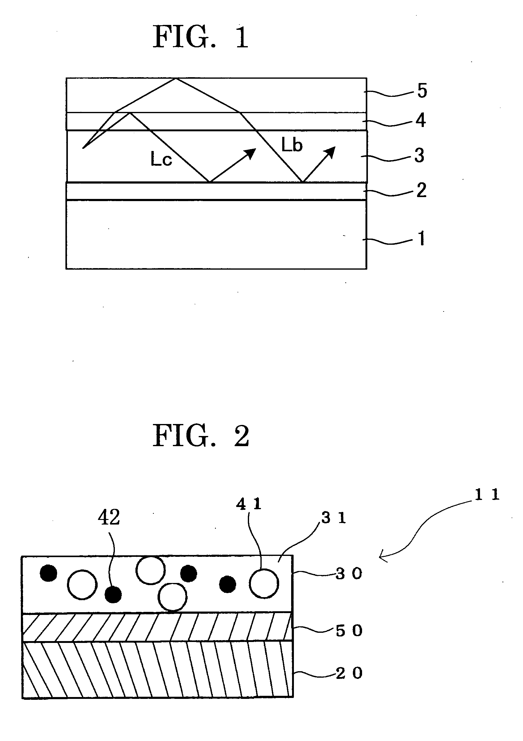
[0031]As described in the section of background art, a cause of the low light extraction efficiency in a self light-emitting display device is that light produced inside the display device causes a total reflection due to a large angle of light incident on an interface with an adjacent layer differing in the refractive index and the light is entirely waveguided through the inside of the display derive and cannot be extracted to the outside.
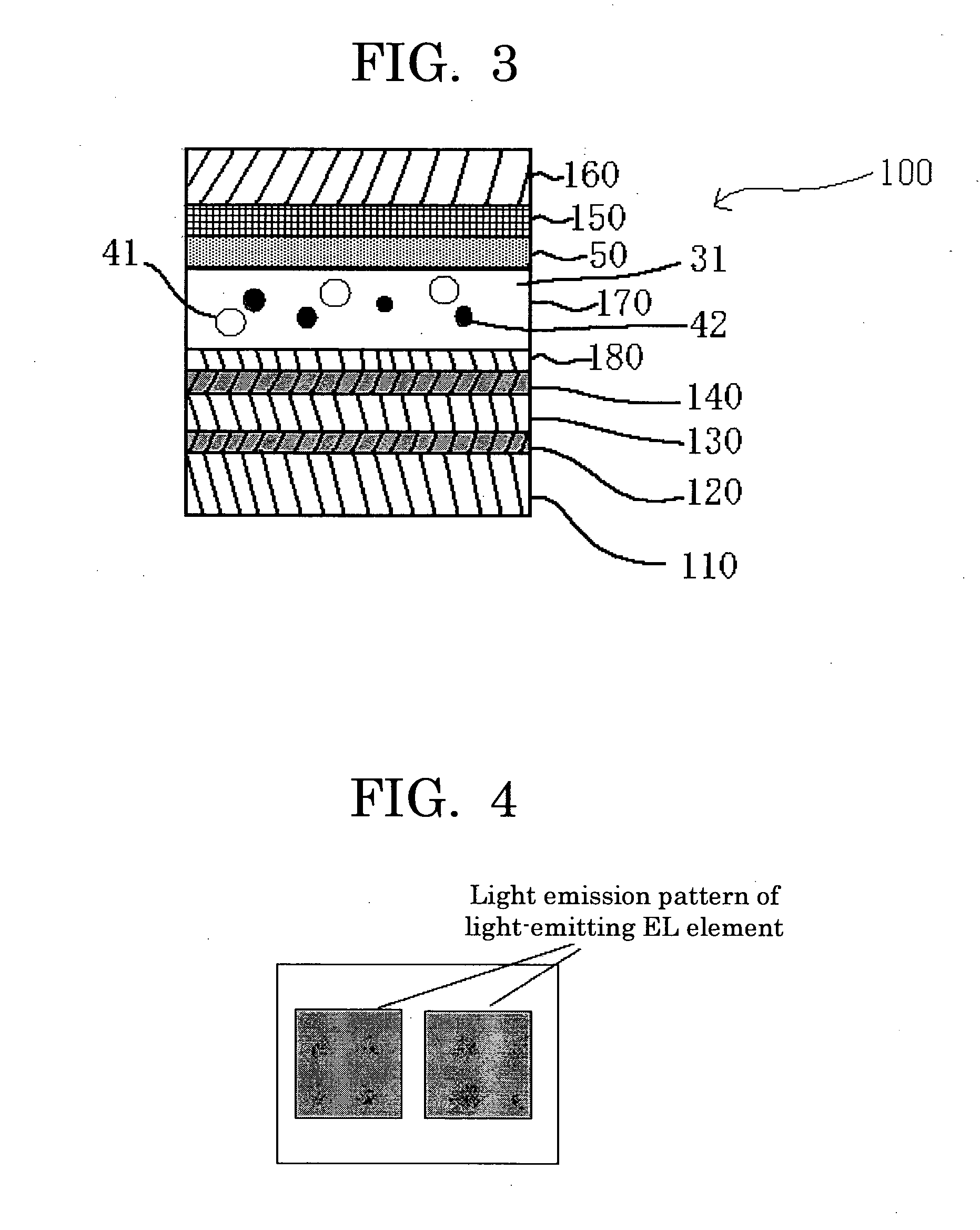
[0032]On the other hand, by introducing, in the organic EL display device, a light diffusion layer containing a binder resin and a light scattering particle, it is possible to extract the light to the outside. That is, the traveling direction of light caused to be waveguided through layers due to total reflection is bent by the action of light scattering, whereby light extraction to the outside can be realized.
[0033]At this time, by setting the refractive index of the matrix material (excluding the light scattering particle from the constituents of the light diffusion layer) to be equal to or higher than the refractive index of the organic light emitt

Problems solved by technology

Therefore, the light emitted readily causes total reflection or interference at the interface and the light extraction efficiency is less than 20%.
Thus, the majority of light is lost.
However, as shown in FIG. 1, light generated inside the display device causes total reflection depending on the angle of light incident on the interface with an adjacent layer differing in the refractive index, and the light is entirely waveguided through the inside of the display device and cannot be extracted to the outside (light of Lb and Lc in FIG. 1).
That is, only about 19% of the entire li

Method used


Image

  • Optical member, and organic electroluminescence display device provided with the optical member
  • Optical member, and organic electroluminescence display device provided with the optical member
  • Optical member, and organic electroluminescence display device provided with the optical member

Examples


example 1

Production of Optical Member 2

>

[0280]Into 93 parts by mass of a thermally crosslinkable fluorine-containing polymer having a refractive index of 1.42 (JN-7228, produced by JSR Corporation), 8 parts by mass of MEK-ST (methylethylketone (MEK) dispersed product of SiO2 sol having an average particle diameter of 10 nm to 20 nm and a solid content concentration of 30 parts by mass, produced by Nissan Chemical Industries Ltd.), and 100 parts by mass of methylethylketone were added, stirred and then filtered through a polypropylene filter having a pore size of 1 μm, thereby preparing a low-refractive-index layer coating liquid.

[0281]The low-refractive-index layer coating liquid thus prepared was applied onto the barrier layer of the transparent PEN substrate provided with a barrier layer produced in Comparative Example 1 using a bar coater, dried at 80° C., and further thermally crosslinked at 120° C. for 10 minutes to form a low-refractive-index layer (refractive index: 1.43) having a thi...


PUM


Abstract

An optical member according to the present invention includes a transparent substrate provided with a barrier layer, a low-refractive-index layer, and a light diffusion layer, the transparent substrate, the low-refractive index layer and the light diffusion layer being provided in this order, wherein the light diffusion layer includes a light scattering particle and a matrix material containing at least a binder resin, the light scattering particle being dispersed in the matrix material, wherein the low-refractive-index layer has a thickness of 1.2 m or more, and wherein the optical member is used in organic electroluminescence display devices.

Description

TECHNICAL FIELD[0001]The present invention relates to an optical member capable of improving light emission efficiency of an optical electroluminescence display device and to an organic electroluminescence display device provided with the optical member.BACKGROUND ART[0002]The organic electroluminescence display device (otherwise referred to as “organic EL display device”) is a self-emission type display device and used for the purpose of display or lighting. The organic EL display has an advantage in view of display performance, such as high visibility in comparison with conventional CRT or LCD or no viewing angle dependency, and is also advantageous in that the display can be lightweighted or thinned. On the other hand, the organic EL lighting has a possibility that lighting in a heretofore unrealizable shape can be realized by using a flexible substrate, in addition to the advantage such as lightweighting or thinning.[0003]The organic EL display device or inorganic EL display dev...

Claims


Application Information

Patent Timeline
IPC IPC(8): H01J1/62G02B5/02
CPCG02B5/0242H01L51/5268G02B5/0278H10K50/854G02B5/0205H10K50/858
Inventor MATSUNAGA, ATSUSHISANETO, RYUJISAITOH, YUKITONOMURA, TATSUHO
Owner UDC IRELAND
Why Eureka
Try Eureka