Intervertebral implant

Inactive Publication Date: 2011-12-08
KRAUS KILIAN +1
View PDF6 Cites 57 Cited by
  • Summary
  • Abstract
  • Description
  • Claims
  • Application Information

AI Technical Summary

Problems solved by technology

The disadvantage of a solid implant such as a solid cage is obviously that a growth of bones through the implant is not possible, i.e. the implant must permanently take on the supportive function and thus is less effective in the long-term.
If an implant is used as a pure spacer, there is further the risk that the implant sinks in the bone and the desired distance is no longer guaranteed.
These implants, however, have the disadvantage that the bones would have to fill a large cavity, if no bone replacement material is used to fill the implants and therefore the implant would have to take on the supportive function for too long with the above-described disadvantages.
Since blood is the catalyst for the formation of bone but the inner cavity of the cage is filled with bone replacement material and is therefore not sufficiently supplied with blood, a natural growth of bones through the partly with bone replacement material filled cage is insufficient.
This in turn means that a growth of bones through a cage partly filled with bone replacement material does also not take place in the desired manner.
Such embodiments have not been realized previo

Method used


Image

  • Intervertebral implant
  • Intervertebral implant
  • Intervertebral implant

Examples


example 1

Cage

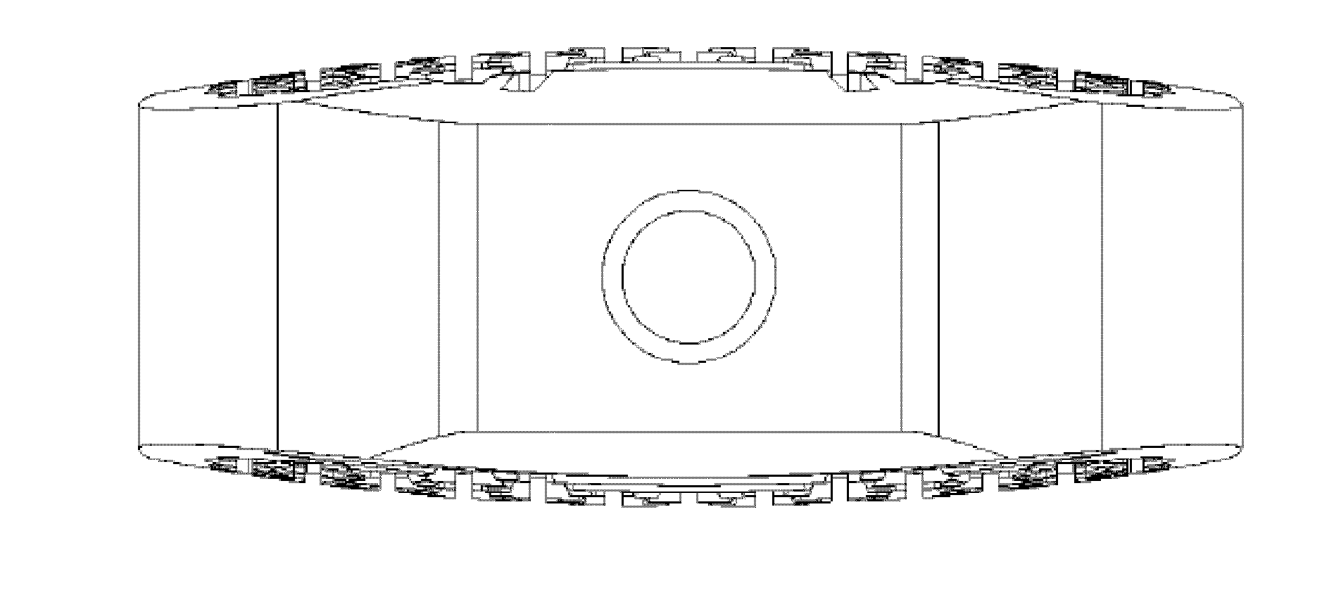
[0148]Example 1 relates to a titanium cage, especially a cervical cage with a longitudinal diameter of 14 mm and a transverse diameter of 12 mm and a height of 8 mm. The Cage is nearly oval and the longitudinal diameter is understood to be the maximum diameter and the transverse diameter is understood to be the smallest diameter.

[0149]The cage is made of titanium with a at least 1.1 mm thick outer sheath and an upper and lower flat surface for contact with the respective vertebral bodies. The outer sheath (7) surrounds the anterior and the posterior side of the implant while the lateral sides do only have an upper and lower frame or ring of the outer sheath (8). In the middle of the lateral sides the inner channel structure starts.

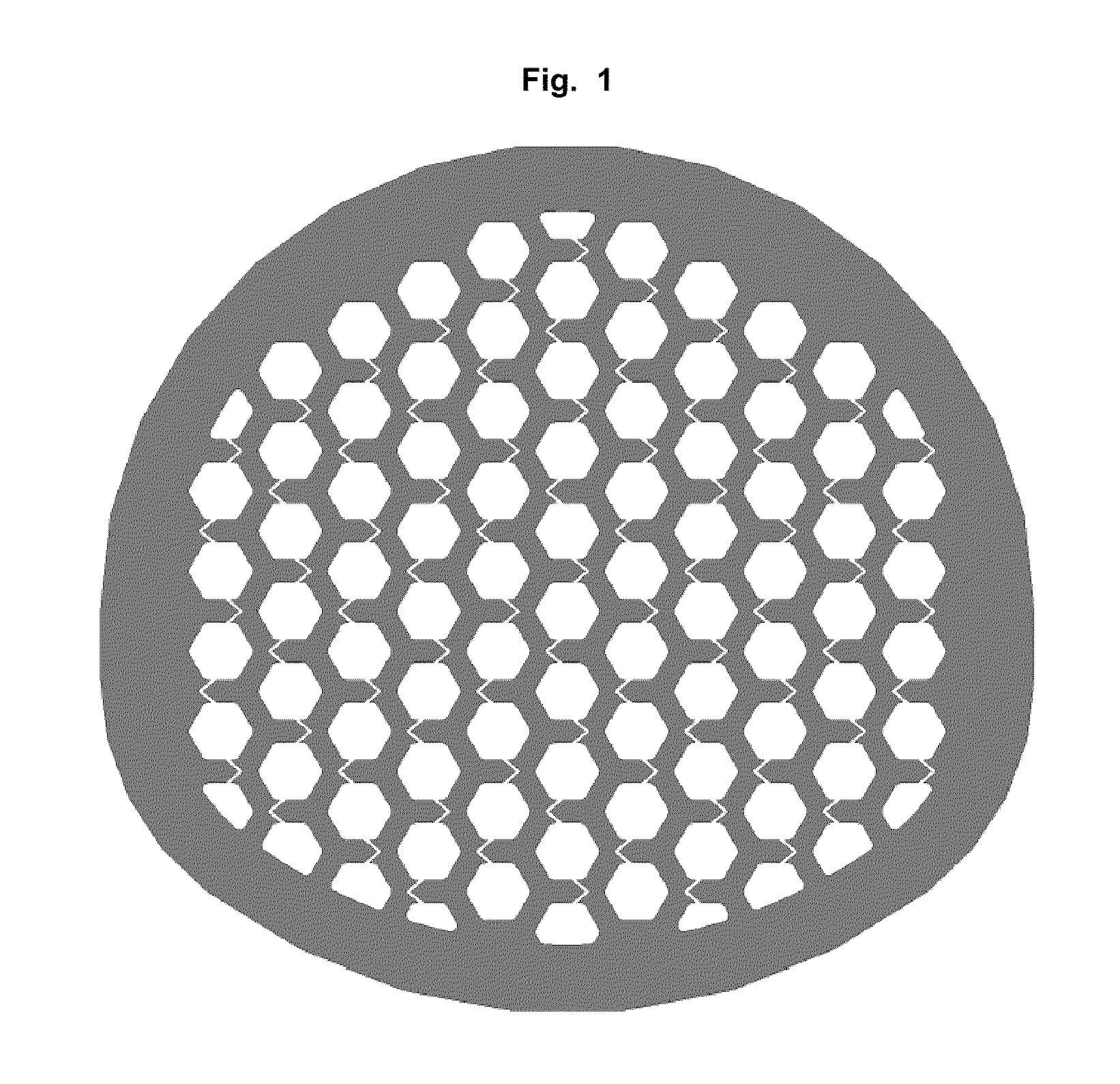
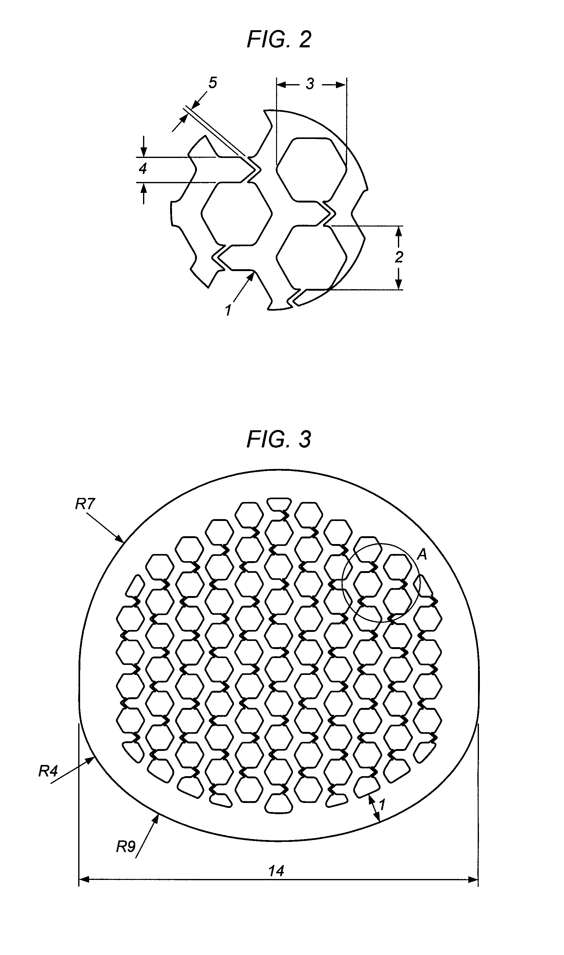
[0150]Inside the cage a honeycomb structure of channels is formed with hexagonal walls. The vertical channels (2) extend in a straight line from the top of the bone-contacting surface to the opposite lower vertebral contacting flat surface. Per cm2 bon...

example 2

Cage

[0154]Example 2 relates to a cage, especially one with a cervical cage of longitudinal diameter 16 mm and a transverse diameter of 13 mm and a height of 9 mm. The cage is nearly oval and the longitudinal diameter is understood to be the maximum diameter and the transverse diameter is understood to be the smallest diameter.

[0155]The cage consists of zirconium with a massive 1.2 mm-thick outer sheath and an upper and lower surface for contact with the respective vertebral bodies. The upper edge of the outer sheath is flat and serves to support the upper vertebral body. The inner channel structure rises from the edge of the outer sheath in a convex shape up to 4 mm beyond the edge of the outer sheath, so that the channel structure in the middle of the cage can press up to 4 mm into the underside of the overlying vertebral body. On the opposite side of the cage the inner honeycomb or canal-type structure also extends like a spherical surface in a convex shape toward the upper surfac...

example 3

Cage

[0161]Example 3 relates to a cage, especially a thoracic cage with a longitudinal diameter of 10 mm and a transverse diameter of 8.8 mm and a height of 6.5 mm. The Cage is nearly oval and the longitudinal diameter is understood to be the maximum diameter and the transverse diameter is understood to be the smallest diameter.

[0162]The Cage consists of surgical stainless steel, with a solid at least 0.9 mm thick outer sheath and an upper and lower flat surface for contact with the respective vertebral bodies, wherein the top and the bottom of the cage has been jagged or serrated with a height of the teeth (9) of about 0.5 mm. Such shaped upper and lower surfaces are shown for example in FIG. 4 and FIG. 10.

[0163]Inside of the cage a channel-type structure is formed from channels with square walls. The vertical channels (2) are divided into two groups. The vertical channels (2) of an inner circle extend in a straight line from the top of the upper vertebral body contacting surface to...


PUM


Abstract

The embodiments herein are directed to bone-joining or bone-bridging intervertebral implants with an inner channel-type structure of channels, which extend from a bone contacting-surface of the implant to the inside of the implant, whereby the vertical channels are connected by horizontal channels which allow a X-ray beam to go through the implant by passing through a horizontal channel.

Description

BACKGROUND OF THE INVENTION[0001]1. Field of the Invention[0002]The present invention is direct to intervertebral implants, so-called cages, with an inner channel-type structure.[0003]2. Description of the Relevant Art[0004]In the prior art solid and hollow implants are known in particular in the area of the spine, which either prevent the ingrowth of bone cells due to their solid structure or have a cavity which is too large to be completely filled with endogenous bone cells within a reasonable time and therefore are usually filled artificially with a bone substitute material or bone chips.[0005]The aim of a fusion is the formation of bones, for instance by cages in the spine area, to achieve as long as possible a stability. The growth of the bones through the implant is insofar advantageous that the bone cells can renew themselves, like elsewhere in the body and thus guarantee a long-term stability. The cages thus serve as a temporary placeholder so that the intervertebral disc sp...

Claims


Application Information

Patent Timeline
IPC IPC(8): A61F2/44
CPCA61F2/4465A61F2310/00155A61F2002/3008A61F2002/30144A61F2002/302A61F2002/30594A61F2002/30617A61F2002/30769A61F2002/30904A61F2002/3092A61F2002/3093A61F2002/3097A61F2310/00017A61F2310/00023A61F2310/00029A61F2310/00047A61F2310/00089A61F2310/00095A61F2310/00125A61F2310/00131A61F2310/00149A61F2002/30062A61F2002/30143
Inventor KRAUS, KILIANKLOSS, HENNING
Owner KRAUS KILIAN
Why Eureka
Try Eureka