Grid plate for lead acid storage battery, plate, and lead acid storage battery provided with same plate

a lead acid storage battery and lead acid technology, applied in the direction of lead-acid accumulator electrodes, cell components, basic electric elements, etc., can solve the problems of acid storage battery to the end of its service life, disadvantageous lithium ion batteries and nickel-hydrogen batteries in terms of price, etc., to increase the mechanical strength of the grid, reduce the effect of mechanical strength

Active Publication Date: 2011-12-15
SHIN KOBE ELECTRIC MASCH CO LTD
View PDF1 Cites 9 Cited by
  • Summary
  • Abstract
  • Description
  • Claims
  • Application Information

AI Technical Summary

Benefits of technology

[0057]In accordance with the present invention, at least the longitudinal grid strands or the lateral grid strands are composed of thick strands and thin strands. Therefore, mechanical strength can be imparted to the thick-strand portions that withstand corrosion of a greater length of time, the shape of the grid can be maintained, and the function of holding the active material in the grid can be maintained over a longer period of time in comparison with the case in which all of the grid strands have been formed using thin strands, even when corrosion of the thin strand portions has progressed and the mechanical strength has been reduced.
[0058]Also, in accordance with the present invention, thick strands and thin strands are arrayed so that the grid strands adjacent to the thick strands are thin strands. Therefore, considerable space can be ensured in order to allow active material paste to flow to the sides of the thick strands, and when the active material is packed from one surface side of the grid plate, the active material can be made to smoothly flow to the other surface side of the grid plate.
[0059]In particular, in accordance with the present invention, the end portion of one end side and the end portion of the other end side in the thickness direction of the plurality of thick strands are positioned further inward in the thickness direction than the end face of the one end side and the end face of the other end side, respectively, in the thickness direction of the frame section. Therefore, the two ends of the thick strands in the thickness direction can be embedded in the active material when the active material is packed into the grid plate. Also, in the present invention, the plurality of thin strands are arranged in a state in which the respective end portions of one end side in the thickness direction are positioned in positions closer to the plane in which the end portions of one end side of the plurality of thick strands in the thickness direction are arranged. Therefore, considerable space can be obtained below the thin strands when the active material is to be packed into the grid plate, and the active material that has flowed below the thin strands can readily flow below the thick strands. Therefore, in accordance with the present invention, the thick strands and the thin strands can be reliably embedded in the active material, and it is possible to eliminate the possibility of a situation in which a portion of the grid strands is exposed.
[0060]As described above, in accordance with the present invention, the grid is composed of thin strands and thick strands to increase the mechanical strength of the grid, and a structure is used in which the thin strands and the thick strands are reliably embedded in the active material. Therefore, it is possible to provide resistance to corrosion over a long period of time and the function for holding the active material in the grid can be maintained. The end portions of one end side of the thin strands in the thickness direction are positioned in positions closer to the plane in which end portions of one end side of the thick strands in the thickness direction have been arranged, whereby the active material more readily flows to the end portion side in the thickness direction of the thick strands, which have been placed facing downward when the active material is to be packed. Therefore, a state in which a portion of the grid strands is exposed can be reliably prevented when the active material is packed, and plates in which all of the grid strands have been completely covered with active material can be manufactured with good yield. The service life of a battery can be considerably extended beyond that of conventional examples by forming a plate (the positive plate in particular) for a lead acid storage battery using the grid body according to the present invention, and it is also possible to achieve a long-life lead acid storage battery having about the same service life as the service life of a wind power generation apparatus, a solar power generation apparatus, or other power generation means that uses natural energy, which has been impossible to achieve using conventional techniques.

Problems solved by technology

However, lithium ion batteries and nickel-hydrogen batteries are disadvantageous in terms of price, and in the particular case of lithium ion batteries, sufficient consideration must be given safety issues.
When the components of the lead acid storage battery degrade with use over time, the lead acid storage battery eventually reaches the end of its service life.
A main cause that brings a lead acid storage battery to the end of its service life is corrosion (generation of PbO2 by oxidation) of the grid plate (mainly the grid plate of the positive plate).
PbO2 has electroconductivity, on the other hand the mass of it is fragile.
However, when the distance between individual grid strands is excessively narrow, the active material has difficultly flowing through the gaps between the grid strands when the paste-form active material is packed into the grid plate, the grid strands overall can no longer be embedded in the active material, and portions of the grid strands are liable to remain exposed.
When the number of grid strands is excessively high, the quantity of active material required to obtain a predetermined battery capacity can no longer be packed into the grid plate.
In the case that all of the grid strands have the same thickness, as shown in FIG. 12, the mechanical strength of the grid overall is reduced, the grid strands break, and original shape of the strands inside the frame section can no longer be maintained, whereupon the active material falls away when corrosion of the grid strands advances and the end of service life approaches.
Therefore, the expected service life period may be unachievable.
Therefore, it becomes difficult to cause the active material to smoothly flow between grid strands when the active material paste is packed into the grid plate from above in a state in which the thickness direction of the grid plate is oriented in the longitudinal direction.
Conductivity between the grid strands and the active material is obstructed when a passive film is formed on the entire periphery of the grid strands.
Therefore, charging is no longer possible, which leads to premature capacity loss (PCL) of the battery and the loss of ability to respond to demand when the service life of the battery is prolonged.
When all of the grid strands are made thick, the amount of active material that can be packed into a grid plate is reduced and therefore leads to reduced battery capacity.
It is possible to consider arranging the thick strands with a greater distance d between strands, but when the distance between grid strands is excessive, the collection characteristics of the grid strands are reduced, the flow of electrons between the grid strands and the active material is insufficient, the charging and discharging reactions of the active material are less likely to occur, and the charge and discharge characteristics of the battery are unavoidably reduced.
However, with a conventional grid plate in which the grid strands are composed of thick strands and thin strands, the two ends of the thick strands in the thickness direction are unavoidably exposed without being covered by active material when the active material is packed into the grid plate.
Therefore, premature capacity loss in the battery is unavoidable.

Method used


Image

  • Grid plate for lead acid storage battery, plate, and lead acid storage battery provided with same plate
  • Grid plate for lead acid storage battery, plate, and lead acid storage battery provided with same plate
  • Grid plate for lead acid storage battery, plate, and lead acid storage battery provided with same plate

Examples


example 1

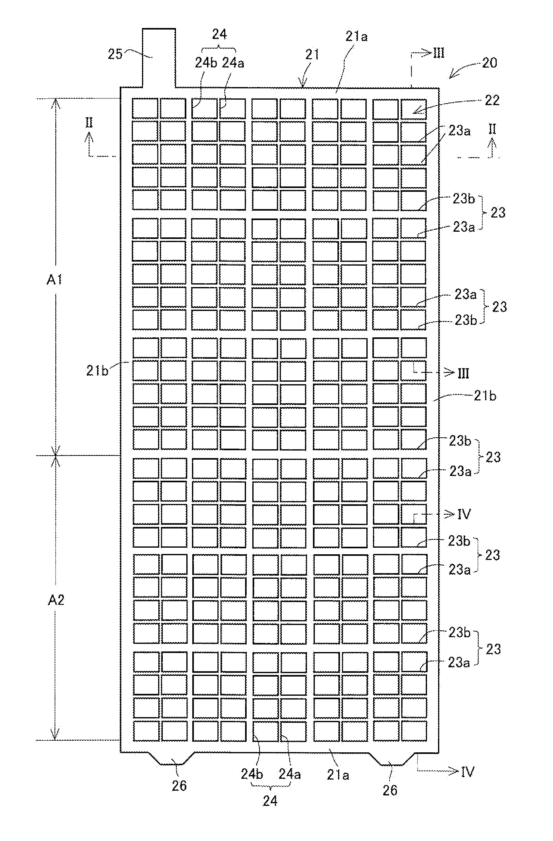
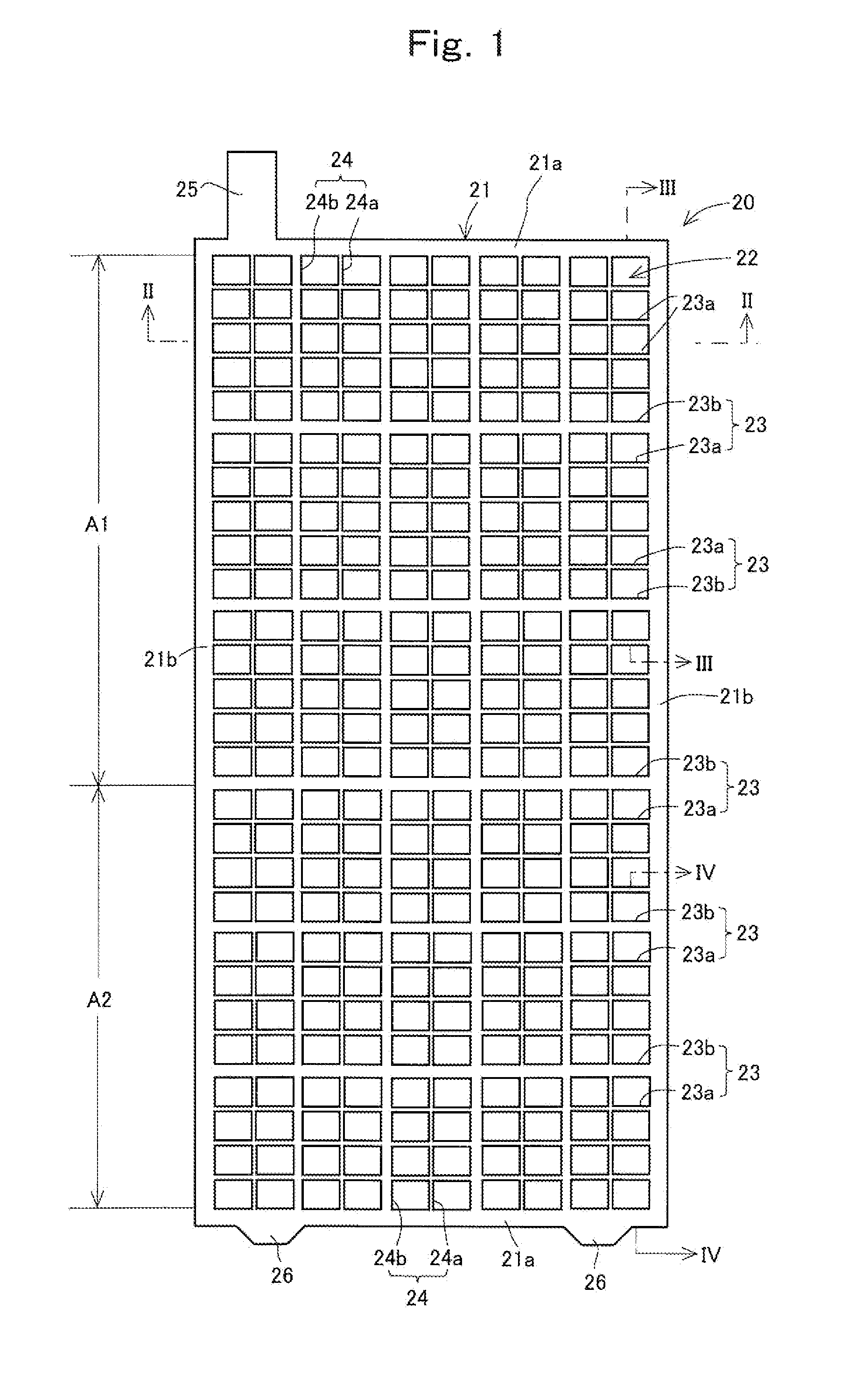
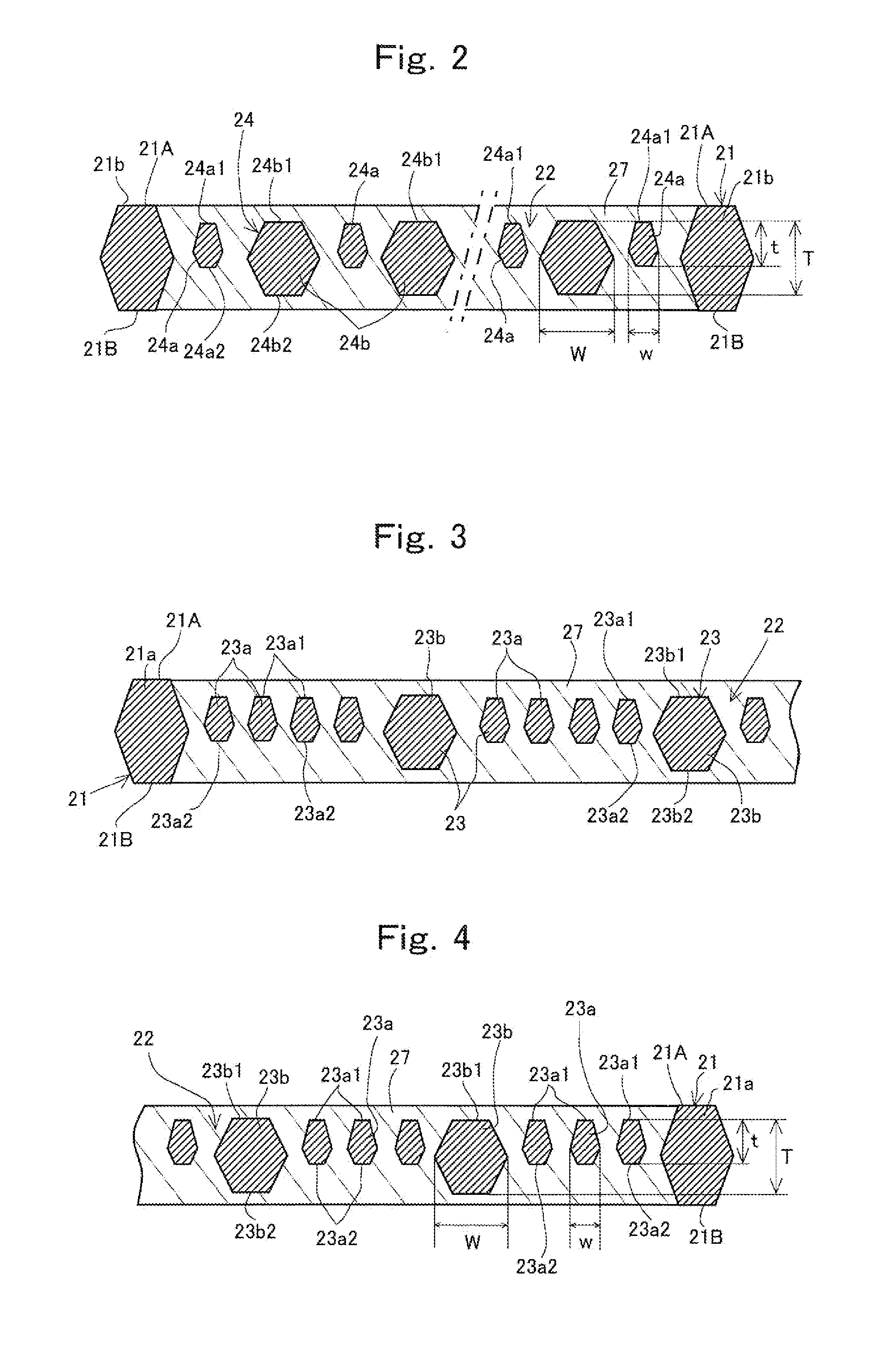
[0153]In the grid plate C, the longitudinal grid strands and the lateral grid strands were disposed inside the grid strands in the pattern shown in FIG. 1. In the same manner as the grid plate B, the longitudinal dimension of the frame section was 385 mm, the lateral dimension was 140 mm, the thickness was 5.8 mm, and the width was 4.4 mm. Longitudinal grid strands and lateral grid strands having thick strands and thin strands, as shown in FIG. 1, were formed inside the grid strands. The cross-sectional shape of the thick longitudinal strands 24b and the thick lateral strands 23b was a hexagonal shape in which the thickness was greater than the width. The thickness was 5.4 mm and the width was 4.3 mm. The cross-sectional shape of the thin longitudinal strands 24a and the thin lateral strands 23a was a hexagonal shape in which the thickness was greater than the width. The thickness was 3.6 mm and the width was 2.8 mm. In the grid plate C, the end faces 24a1, 23a1 of one end side in t...

example 2

[0154]In the grid plate D, the longitudinal dimension of the frame section was 385 mm, the lateral dimension was 140 mm, the thickness was 5.8 mm, the width was 4.4 mm, as with the grid plate B. Among the strands formed inside the frame section, the cross-sectional shape of the lateral grid strands was a hexagonal shape in which the thickness was greater than the width in the same manner as the grid plate A (FIG. 12), and all of the lateral grid strands had a thickness of 3.2 mm and a width of 2.4 mm. The number of lateral grid strands was 26. On the other hand, thick longitudinal strands and thin longitudinal strands were provided as the longitudinal grid strands, and the cross-sectional shape of the thick longitudinal strands and the thin longitudinal strands was a hexagonal shape in which the thickness was greater than the width, as with the grid plate C. In this case, the thickness of the thick longitudinal strands was 5.4 mm and the width was 4.3 mm; and the thickness of the th...

example 3

[0155]In the grid plate E, the longitudinal dimension of the frame section was 385 mm, the lateral dimension was 140 mm, the thickness was 5.8 mm, and the width was 4.4 mm in the same manner as the grid plate B. Among the grid strands formed inside the frame section, the longitudinal grid strands were formed using similarly configured strands having a hexagonal cross-section measuring 3.2 mm in thickness and 2.4 mm in width, as with the grid plate A. On the other hand, thick lateral strands and thin lateral strands were provided as the lateral grid strands, the thick lateral strands having a hexagonal cross-sectional shape with thickness of 5.4 and a width of 4.3 mm in the same manner as the grid plate C, and the thin lateral strands having a hexagonal cross-sectional shape with a thickness of 3M mm and a width of 2.8 mm. In this case as well, the end portions 24a1, 23a1 of one end side in the thickness direction of the thin longitudinal strands 24a and the thin lateral strands 23a,...


PUM

PropertyMeasurementUnit
voltageaaaaaaaaaa
thicknessaaaaaaaaaa
sizeaaaaaaaaaa

Abstract

A grid plate for a lead acid storage battery comprising a frame section having a pair of quadrangular contour shape, and longitudinal grid strands and lateral grid strands that form a grid inside the frame section. The longitudinal grid strands and lateral grid strands are composed of thick strands of smaller thickness than the frame section, and thin strands of smaller width and thickness than the thick strands. The thick strands and thin strands are arranged so that the strands adjacent to the thick strands are thin strands, and space is reliably provided for facilitating the flow of active material to the sides of the thick strands. The two ends of the thick strands in the thickness direction are positioned further inward from the two end faces of the frame section in the thickness direction, and the end portions of one end side of the thin strands in the thickness direction are positioned in positions offset to one end side of the thick strands in the thickness direction, whereby the active material is readily packed into the reverse surface side of the grid plate.

Description

TECHNICAL FIELD OF THE INVENTION[0001]The present invention relates to a grid plate for a lead acid storage battery, a plate, and a lead acid storage battery provided with the plate.PRIOR ART OF THE INVENTION[0002]Batteries can be roughly divided into primary batteries typified by manganese, mercury, alkaline, and the like; and chargeable secondary batteries typified by nickel-cadmium, lithium ion, nickel-hydrogen, and the like.[0003]Currently, lithium ion batteries, nickel-hydrogen batteries, and other small, high-performance batteries are being developed as next-generation secondary batteries widely used in cellular telephones and the like. However, lithium ion batteries and nickel-hydrogen batteries are disadvantageous in terms of price, and in the particular case of lithium ion batteries, sufficient consideration must be given safety issues. Therefore, valve regulated lead acid storage batteries are widely used as batteries in backup power sources disposed in office buildings, h...

Claims


Application Information

Patent Timeline
Patent Type & Authority Applications(United States)
IPC IPC(8): H01M4/73
CPCH01M4/73Y10T29/10H01M4/72Y02E60/12H01M10/06Y02E60/10H01M4/14H01M10/12
Inventor WAKATABE, HIROYUKIMITANI, KATSURASANO, SHINICHIHIROSE, YOSHIKAZUSHIMOURA, ICHIRO
Owner SHIN KOBE ELECTRIC MASCH CO LTD
Why Eureka
Try Eureka