
Defoaming method

a foaming method and foam technology, applied in the field of foaming methods, can solve the problems of insufficient time available for destroying foam, foam remains, and difficult to decrease the amount of oxygen in the headspace, and achieve the effects of short time, high speed, and reliable generation

Active Publication Date: 2011-12-15
TOYO SEIKAN KAISHA LTD
View PDF2 Cites 8 Cited by
  • Summary
  • Abstract
  • Description
  • Claims
  • Application Information

AI Technical Summary

Benefits of technology

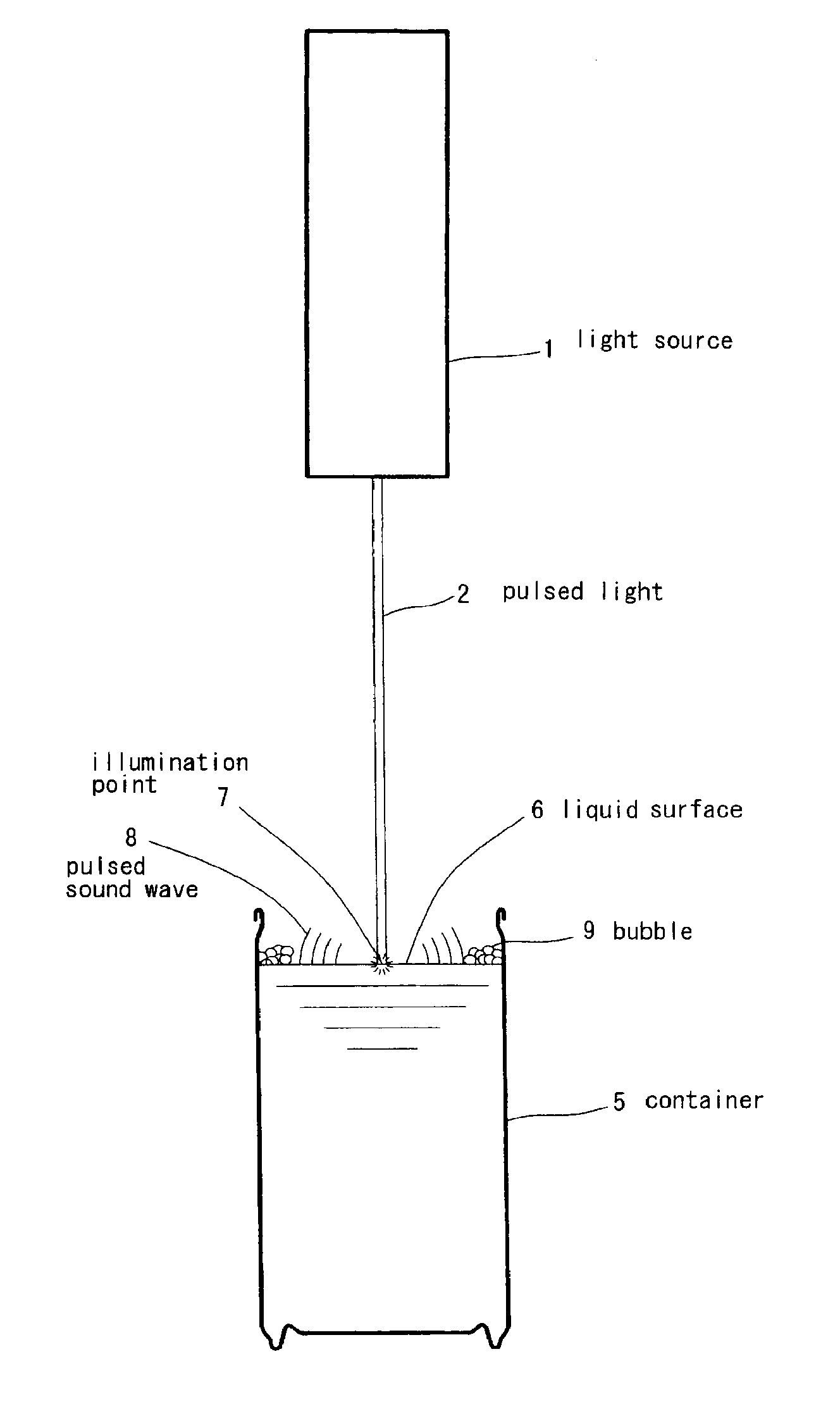
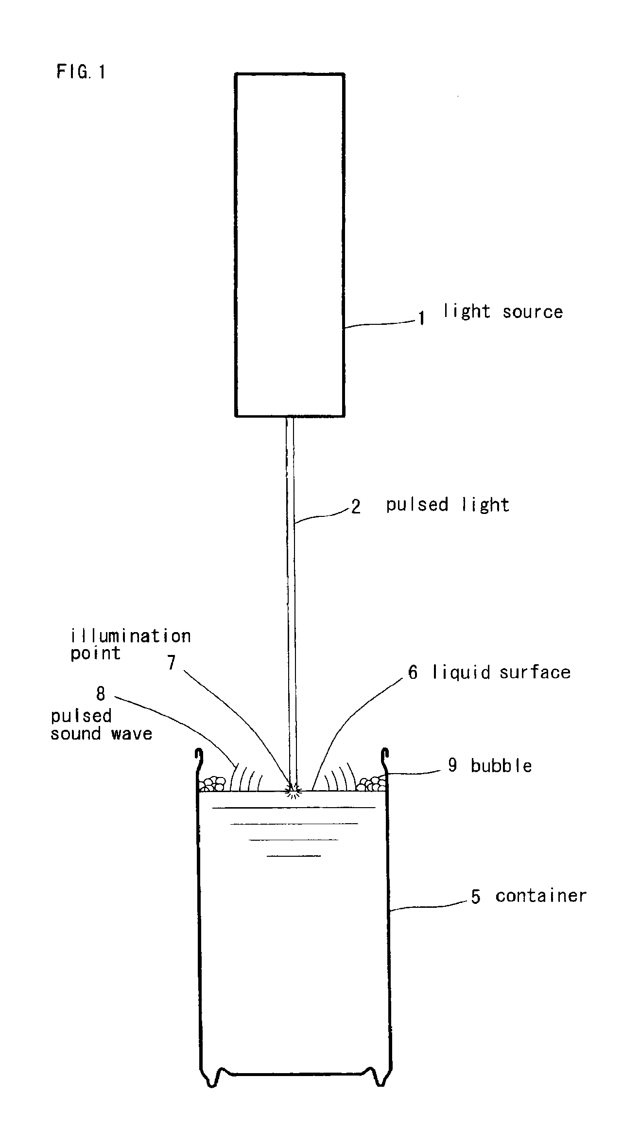
[0024]According to these aspects of the invention a pulsed sound wave that is accompanied by strong pressure variations from a sound source propagates as a spherical surface wave and can destroy the bubbles, thereby ensuring defoaming. Therefore, by contrast with the conventional process in which defoaming is performed by light irradiation, for example, with a laser beam, it is not necessary to irradiate each bubble with a beam. Therefore, defoaming can be performed rapidly and within a short time. Further, because the pulsed sound wave propagated to the inner peripheral surface of the container, even foam located in the vicinity of the inner peripheral surface of the container that has been difficult to destroy by the conventional methods can be effectively destroyed.
[0025]In addition to the above-described effect, the pulsed sound wave is generated by irradiation with pulsed light. Therefore, the pulsed sound wave can be generated reliably at a high speed with a simple device.
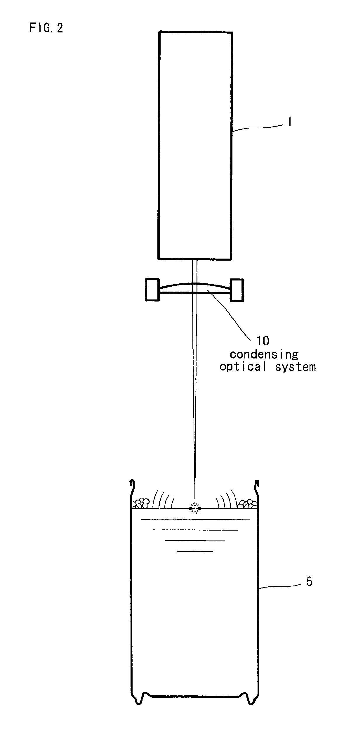
[0026]According to another aspect the invention the beam power density per unit surface area can be increased by irradiating with a condensed pulsed light and the pulsed sound wave can be generated with better energy efficiency.
[0027]According to another aspect of the invention breakdown is induced and defoaming is performed by condensing the pulsed light on the gas portion above the liquid surface. Therefore, the impact on the liquid surface is decreased by comparison with the case in which the liquid surface is directly irradiated with a laser beam and liquid droplets are prevented from scattering and adhering to the device or to the glass members of the laser irradiation aperture. Therefore, this aspect of the invention is especially useful for maintaining a sanitary level of the device and optical characteristics.
[0028]According to another aspect of the invention by irradiating the liquid surface with pulsed light, it is possible to break rapidly the bubbles in the vicinity of the illumination point and also rapidly break the bubbles located at a distance from the optical path by the pulsed sound wave generated at the time of irradiation, thereby enabling efficient high-speed defoaming
[0029]According to another aspect of the invention the liquid surface can be reliably irradiated with pulsed light even in the case of a narrow-mouth container and a pulsed sound wave can be generated inside the headspace of the narrow-mouth container. Therefore, defoaming inside narrow-mouth containers that has conventionally been difficult can be also performed reliably.

Problems solved by technology

Foam generation behavior and destruction behavior differ depending on the properties of individual beverages and filling conditions, but typically when the production rate is high, a large amount of foam is generated, the available time is insufficient for destroying the foam, and foam remains during sealing.
Foam contains oxygen at the same concentration level as the air, and because the oxygen contained in the foam cannot be removed by gas displacement in the headspace, the foam makes it difficult to decrease the amount of oxygen in the headspace.

Method used


Image

  • Defoaming method
  • Defoaming method
  • Defoaming method

Examples


example 1

[0068]The basic wave of a Q-switched YAG laser was converged with a convex lens with a focal distance of 300 mm, and the liquid surface of coffee filled in a can (opening diameter 50 mm) with a capacity of 200 g was irradiated. The liquid surface was covered with foam having a height of 10 mm over the entire mouth portion. The laser beam had a wavelength of 1064 nm, a pulse width of 5 ns, a repetition period of 10 Hz, and an average beam power of 1 W. The beam diameter in the focus position was 200 μm, and the beam power density per unit surface area was 5 GW / cm2. When the liquid surface was irradiated with 10 shots of such light beam, the foam was completely destroyed and the entire liquid surface was exposed.

example 2

[0069]The liquid surface of coffee filled in a PET bottle (mouth diameter 20 mm, body diameter 80 mm) with a capacity of 500 mL was irradiated in the same manner as in Example 1. The liquid surface was covered with foam having a height of 15 mm over the entire head space. When the liquid surface was irradiated with 10 shots of such light beam, the foam was completely destroyed and the entire liquid surface was exposed.

[0070]Examples 1, 2 confirmed that the method in accordance with the present invention enables instantaneous defoaming even of coffee beverages on which the bubbles are comparatively difficult to break down and also when the entire liquid surface in the container is covered with foam. Further, foam located on the wall surface circumference of a container is not easy to destroy by the conventional methods, but this foam is also reliably destroyed in the examples. Moreover, as shown in Example 2, defoaming in a narrow-mouth container can be performed as effectively as in...

example 3

[0071]The basic wave (beam diameter 9 mm) of a Q-switched pulsed YAG laser was converged with an aplanat convex lens with a focal distance of 150 mm, the beam was converged 10 mm above the liquid surface of green tea beverage filled in a can (opening diameter about 50 mm) with a capacity of 200 g, and laser induced breakdown (LIB) was generated. Foam with a thickness of about 5 mm remained along the edge with the side wall on the liquid surface of the green tea beverage.

[0072]The laser beam was in a Gaussian mode and had a laser wavelength of 1064 nm, a pulse width of 5 ns, a repetition period of 10 Hz, and an average beam power of 1 W. Thus, the light energy per one pulse was 100 mJ. With one-shot irradiation of the pulse, the entire foam present on the liquid surface was destroyed by the sound wave generated by LIB.

[0073]Further, when the laser beam was converged on the liquid surface under the same conditions, the foam could be completely destroyed at 50 mJ.


PUM


Abstract

A defoaming method capable of destroying foams generated when a container is filled with drink, or the like, efficiently at a high speed and destroying foams effectively even in the case of a container having a narrow mouth. Liquid surface (6) in a container (1) is irradiated with pulse-like light (2) and a pulse-like sound wave (8) is generated from an irradiated point (7) as a sound source. The pulse-like sound wave thus generated propagates from the sound source as a strong spherical wave to reach a bubble (9) and to destroy the bubble. It can also destroy a bubble located at a place remote from the optical path quickly, thus destroying bubbles efficiently at a high speed. Alternatively, pulse-like light is condensed at a gas portion above the liquid surface and the bubbles can be destroyed with a shock wave generated by breakdown phenomenon.

Description

CROSS REFERENCE TO RELATED APPLICATIONS[0001]This application is a divisional application of U.S. application Ser. No. 12 / 162,075, filed Jul. 24, 2008, which is a National Stage of PCT / JP2007 / 050904, filed Jan. 22, 2007, based upon and claims the priority of the prior Japanese Patent Application No. 2006-017879, filed Jan. 26, 2006, the entire contents of which are incorporated herein by reference.TECHNICAL FIELD[0002]The present invention relates to a defoaming method, and more particularly to a defoaming method suitable for destroying foam generated when a container such as a can, a PET bottle, a bottle can, and a pouch is filled with a liquid such as a beverage.BACKGROUND[0003]In a filling process of producing packaged beverages (canned beverages, beverages in PET bottles, bottled beverages), the beverage is typically caused to flow from above into a container disposed vertically in a filling machine (filler) and then the container is joined to a lid member and sealed in a sealin...

Claims


Application Information

Patent Timeline
Patent Type & Authority Applications(United States)
IPC IPC(8): B01D19/02
CPCB01D19/0073B01D19/0078B67D1/1422B67C3/22B01D19/02Y10T137/0385Y10T137/2984Y10T137/299B01D19/00B67C3/00
Inventor TAKENOUCHI, KENYUASA, YOSHIYUKI
Owner TOYO SEIKAN KAISHA LTD
Learn More