Method and plant for amine emission control

a technology of amine emission control and plant, applied in the field of co2 capture and sequestration, can solve the problems of low absorption rate of cosub>2 /sub>, and low absorption rate of cosub>2 /sub>, and achieve the effect of reducing or eliminating the emission of amines

Active Publication Date: 2011-12-22
AKER CARBON CAPTURE NORWAY AS
View PDF1 Cites 59 Cited by
  • Summary
  • Abstract
  • Description
  • Claims
  • Application Information

AI Technical Summary

Benefits of technology

[0017]According to a first aspect, the present invention relates to a method for eliminating or substantially reducing emission of amines and alkaline degradation products thereof, to the atmosphere from a plant for CO2 capture from a flue gas, where the CO2 is captured by countercurrent flow to an absorbent in an absorption zone, the absorbent comprising an aqueous solution of one or more amine(s), to give a CO2 lean flue gas that is released into the surroundings, and a CO2 rich absorbent that is regenerated in a regeneration column to give a CO2 rich gas that is treated further, and regenerated absorbent that is recycled to the absorption zone, wherein the CO2 lean flue gas is washed with an acidic aqueous solution to remove or substantially reduce the amount of amine(s) and alkaline degradation products thereof in the gas.

Problems solved by technology

The absorption rate of CO2 is, however, low and the CO2 partial pressure in the flue gas in the upper part of the absorber is low, hence the amount of absorbed CO2 in the wash water section is not sufficient to eliminate the amine backpressure.

Method used


Image

  • Method and plant for amine emission control
  • Method and plant for amine emission control
  • Method and plant for amine emission control

Examples


example 1

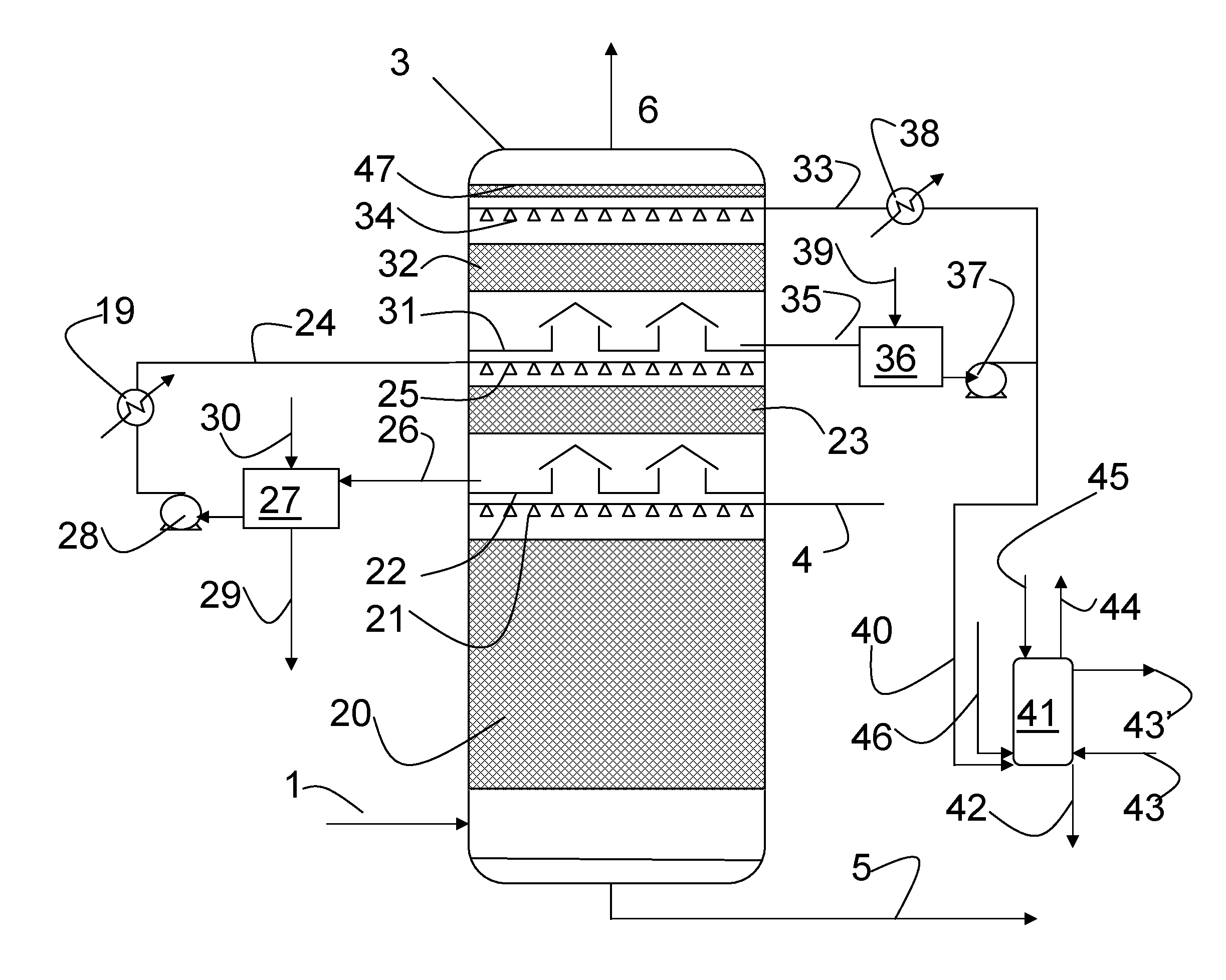
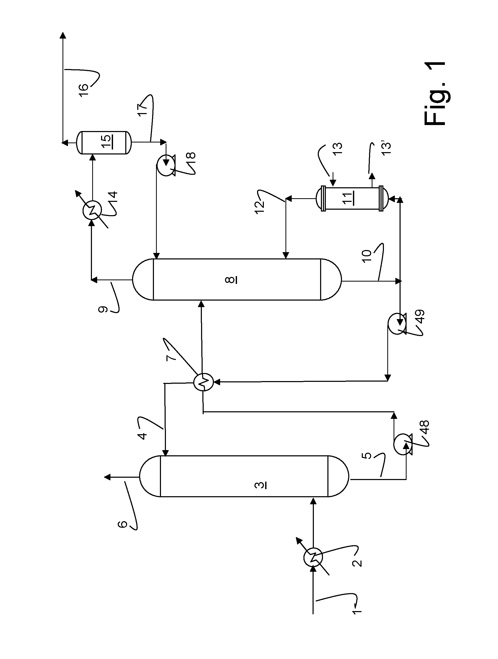
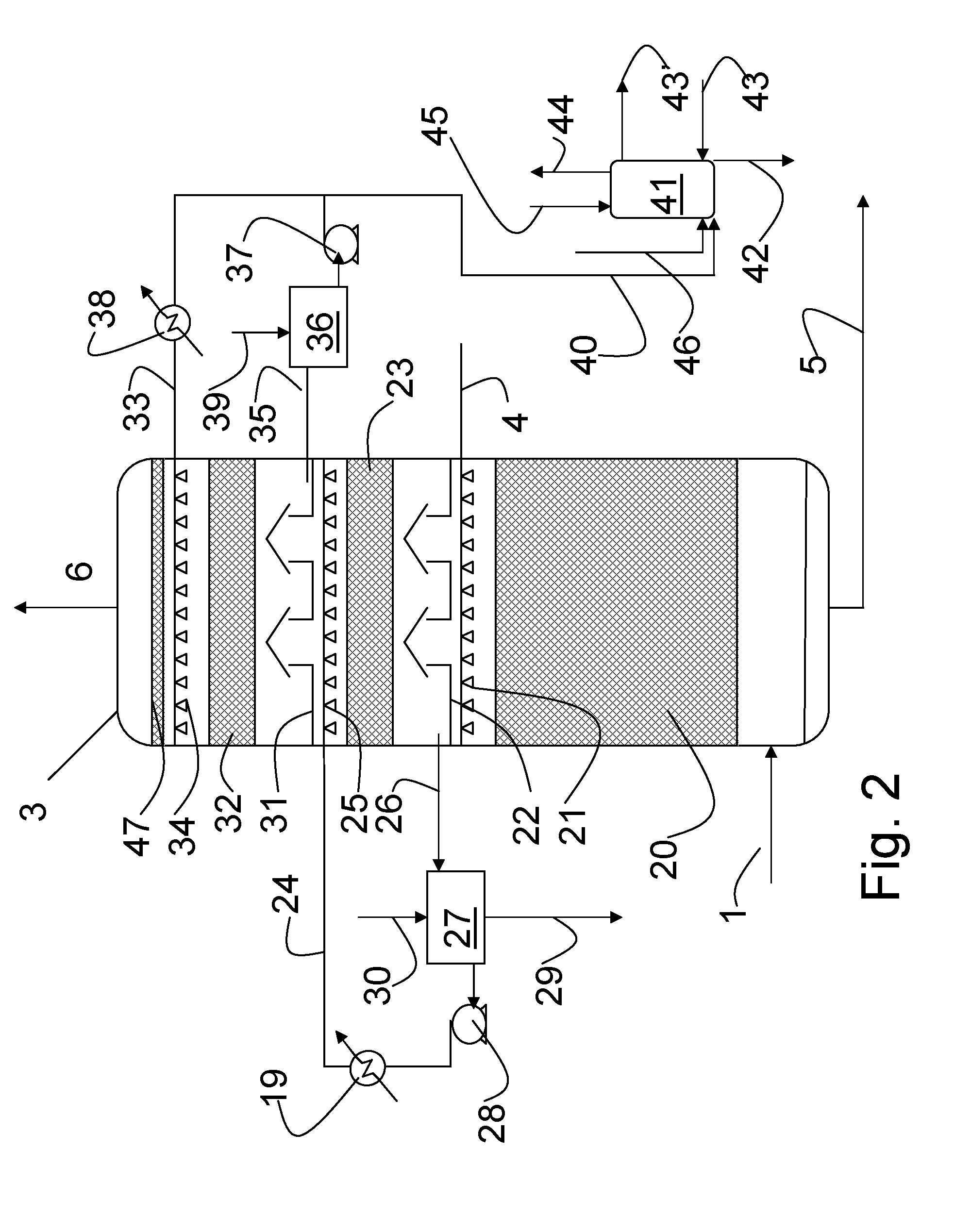
[0071]A pilot scale CO2 capture plant according to FIG. 1 was used for the tests. 30 wt % MEA solvent was applied for capturing CO2 from a gas turbine exhaust gas. The CO2 absorber consists of a main absorption zone, where 90% CO2 capture was achieved.

[0072]The flue gas leaving the absorption zone contained 80-100 ppm of gaseous MEA and the flue gas temperature was in the range 50-55° C. A single water wash section with structured packing was applied for reduction of amine slip to the surroundings. The recycling water was cooled by an external heat exchanger, causing cooling on the passing flue gas and the temperature on the gas leaving the water wash section was in the range 45-50° C. Condensation of water took place in the wash water section, and the excess liquid in the water wash liquid recycling loop was routed to the main amine circulation loop. Steady state conditions for the water wash system (i.e. constant temperature profiles and constant gas and liquid concentrations) was...

example 2

[0074]A pilot scale CO2 capture plant according to FIG. 1 was used for the tests. 30 wt % MEA solvent was applied for capturing CO2 from flue gas from a coal fired power station. The CO2 absorber consists of a main absorption zone, where 90% CO2 capture was achieved.

[0075]The flue gas leaving the absorption zone contained 90-100 ppm of gaseous MEA and the flue gas temperature was in the range 55-57° C. A single water wash section with structured packing was applied for reduction of amine slip to the surroundings. The recycling water was cooled by an external heat exchanger, causing cooling on the passing flue gas and the temperature on the gas leaving the water wash section was in the range 45-50° C. Condensation of water took place in the wash water section, and the excess liquid in the water wash liquid recycling loop was routed to the main amine circulation loop. Steady state conditions for the water wash system (i.e. constant temperature profiles and constant gas and liquid conc...


PUM

PropertyMeasurementUnit
temperatureaaaaaaaaaa

Abstract

A method for eliminating or substantially reducing emission of amines (amineslip) and alkaline degradation products to the atmosphere from a plant for CO2 capture from a flue gas, where the CO2 is captured by counter-current flow to an absorbent in an absorption zone, the absorbent comprising an aqueous solution of one or more amine(s), to give a CO2 lean flue gas that is released into the surroundings, and a CO2 rich absorbent that is regenerated in a regeneration column to give a CO2 rich gas that is treated further, and regenerated absorbent that is recycled to the absorption zone, wherein the CO2 lean flue gas is washed with an acidic aqueous solution to remove or substantially reduce the amount of amine(s) and alkaline degradation products thereof in the gas, is described.

Description

TECHNICAL FIELD[0001]The present invention relates to the field of CO2 capture and sequestration. More specifically the present invention relates to an improved method and an improved absorber for reducing the problem related to emissions from amine based CO2 capture plants, which are released into the surroundings by the CO2 depleted exhaust gas being discharged to air.BACKGROUND[0002]The continually increasing combustion of fossil fuel, such as coal, natural gas and oil, during the last centuries has resulted in an increase in the concentration of CO2 in the atmosphere. The increasing concentration of CO2 has caused concern due to the greenhouse effect caused by CO2. The greenhouse effect is suspected already to have caused at least some of the changes in the climate that have been seen during the last decades, and is according to simulation models suspected to cause even more and potentially dramatic changes in the climate of planet earth.[0003]This has caused a call for action f...

Claims


Application Information

Patent Timeline
Patent Type & Authority Applications(United States)
IPC IPC(8): B01D53/14B01D19/00
CPCB01D53/1406B01D53/1475B01D2251/504B01D53/62B01D2251/512Y02C10/06B01D2251/506Y02A50/20Y02C20/40
Inventor GRAFF, OSCAR FREDRIKBADE, OTTO MORTENGORSET, ODDVARWOODHOUSE, SIMON
Owner AKER CARBON CAPTURE NORWAY AS
Why Eureka
Try Eureka