Opto-electro hybrid cable

a hybrid cable and optoelectronic technology, applied in the direction of optics, fibre mechanical structures, instruments, etc., can solve the problems of difficult to sufficiently suppress lateral pressure, increase transmission loss, increase transmission loss, etc., to prevent excessive lateral pressure, increase tensile strength, and prevent excessive tension

Active Publication Date: 2011-12-22
SUMITOMO ELECTRIC IND LTD +1
View PDF3 Cites 58 Cited by
  • Summary
  • Abstract
  • Description
  • Claims
  • Application Information

AI Technical Summary

Benefits of technology

[0017]According to the opto-electro hybrid cable of the invention, it is possible to prevent the excessive lateral pressure from being applied to the optical fibers from the electronic wires and the excessive bending or twisting from being generated. In addition, it is possible to increase the tensile strength and to prevent the excessive tension from being applied to the optical fibers, so that it is possible to keep the favorable transmission characteristics.

Problems solved by technology

However, transmission loss may be increased in the optical fibers configuring the opto-electro hybrid cable due to excessive bending or twisting.
In this case, the transmission loss may be increased.
Accordingly, when the partition sheet is only to be provided to divide the accommodating space between the optical fibers and the electronic wires, as the cable of the second patent document, it is difficult to sufficiently suppress the lateral pressure, which is applied to the optical fibers from the electronic wires, and to thus reduce the increase in the transmission loss.
Also, even when the sheath is provided to divide the accommodating space between the optical fibers and the electronic wires, as the cable of the first patent document, it is difficult to sufficiently suppress the lateral pressure, which is applied to the optical fibers from the electronic wires when bending the cable to a small diameter (a diameter of about 30 mm), and to thus reduce the increase in the transmission loss.

Method used


Image

  • Opto-electro hybrid cable
  • Opto-electro hybrid cable
  • Opto-electro hybrid cable

Examples


example 1

Illustrative Example 1

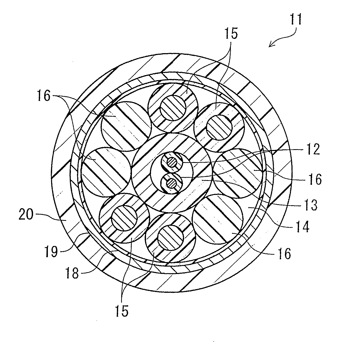
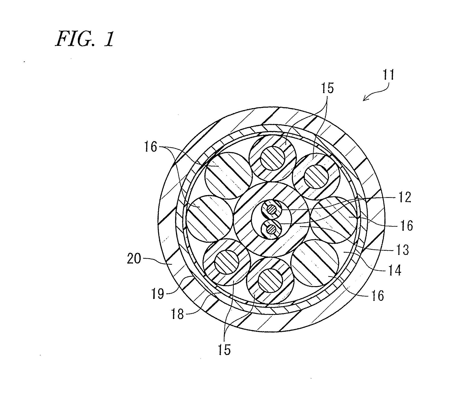
[0062]In the protection tube having Shore D hardness of 70, an inner diameter of about 0.54 mm and a thickness of about 0.23 mm and made of tetrafluoroethylene-ethylene copolymer (ETFE) resin, the three resin coated optical fibers were circumferentially disposed to abut on the inner circumference thereof.

example 2

Illustrative Example 2

[0063]In the protection tube having Shore D hardness of 65, an inner diameter of about 0.50 mm and a thickness of about 0.25 mm and made of tetrafluoroethylene-ethylene copolymer (ETFE) resin, the two resin coated optical fibers were circumferentially disposed to abut on the inner circumference thereof.

example 3

Illustrative Example 3

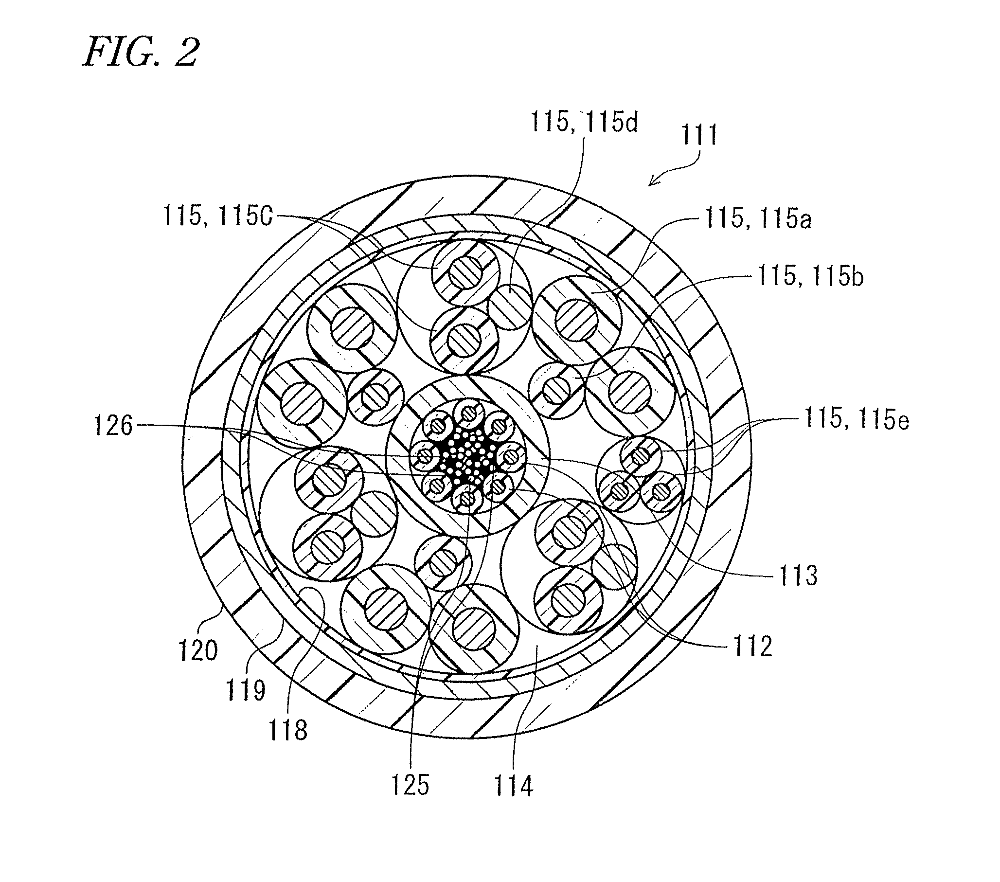
[0074]In the protection tube having Shore D hardness of 65, an inner diameter of about 0.9 mm and a thickness of about 0.6 mm and made of tetrafluoroethylene-ethylene copolymer (ETFE) resin, the eight resin coated optical fibers were circumferentially disposed to abut on the inner circumference thereof. In the gap of the protection tube, the tension members made of aramid fiber having 1420 denier and the fillers made of nylon fiber having 420 denier were accommodated.


PUM


Abstract

An opto-electro hybrid cable is an opto-electro hybrid cable that has a plurality of optical fibers and a plurality of electronic wires inside a sheath. The plurality of optical fibers are accommodated in a tube having Shore D hardness of 65 or greater, the plurality of optical fibers are circumferentially disposed to abut on an inner circumference of the tube, and the plurality of electronic wires are disposed around the plurality of optical fibers.

Description

CROSS-REFERENCE TO RELATED APPLICATIONS[0001]This application claims priority to Japanese Patent Application No. 2010-141378, filed on Jun. 22, 2010 and Japanese Patent Application No. 2010-141401, filed on Jun. 22, 2010. The entire disclosures of Japanese Patent Application No. 2010-141378 and Japanese Patent Application No. 2010-141401 are hereby incorporated herein by reference.BACKGROUND[0002]1. Field of the Invention[0003]The present invention relates to an opto-electro hybrid cable having electronic wires and optical fibers.[0004]2. Background Information[0005]In electronic devices such as medical devices, portable terminals, small video camera, personal computers and PDA (Personal Digital Assistant), as the functions thereof are highly-developed, the high-speed communication is needed. Accordingly, an opto-electro hybrid cable having combined electronic wires and optical fibers is used.[0006]An opto-electro hybrid cable has been known in which a buffer layer is provided on an...

Claims


Application Information

Patent Timeline
Patent Type & Authority Applications(United States)
IPC IPC(8): G02B6/44
CPCG02B6/4416G02B6/446G02B6/4432
Inventor HAYASHISHITA, TATSUNORITAKAHASHI, HIROKAZUNIWATA, MASAMICHI
Owner SUMITOMO ELECTRIC IND LTD
Why Eureka
Try Eureka