Displacement sensor

Active Publication Date: 2011-12-29
INSULET NETHERLANDS BV
View PDF3 Cites 51 Cited by
  • Summary
  • Abstract
  • Description
  • Claims
  • Application Information

AI Technical Summary

Benefits of technology

[0020]In the linear capacitance displacement transducer the electric field created, in use, between the first and second capacitor plates remains stationary whilst the proportion of the space between these plates that is filled with high dielectric material is altered by movement of the dielectric structure. This construction is advantageous in that since the first and second capacitor plates are substantially spatially fixed relative to one another, electrical connections for connecting thereto do not need to move thereby simplifying and making more robust the transducer and improving the reliability of a signal output by the transducer. Additionally, since the second capacitor plate is substantially spatially fixed relative to the electric field created, in use, the secon

Problems solved by technology

Such potentiometric sensors often suffer from the problems of mechanical wear, frictional resistance in the wiper action, limited resolution in wire-wound units, and high electronic noise.
These manufacturing requirements make these transducers expensive to manufacture and have a length dimension at least twice the dis

Method used


Image

  • Displacement sensor
  • Displacement sensor
  • Displacement sensor

Examples


Example

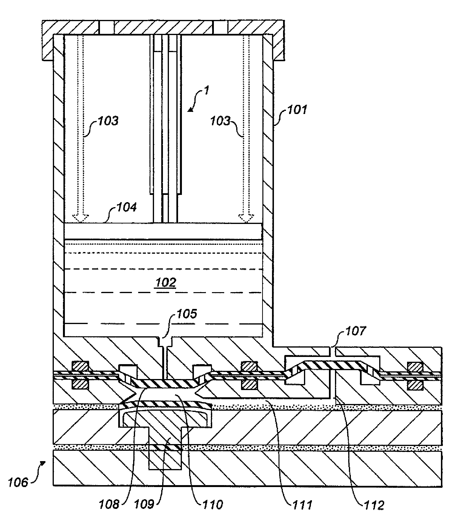
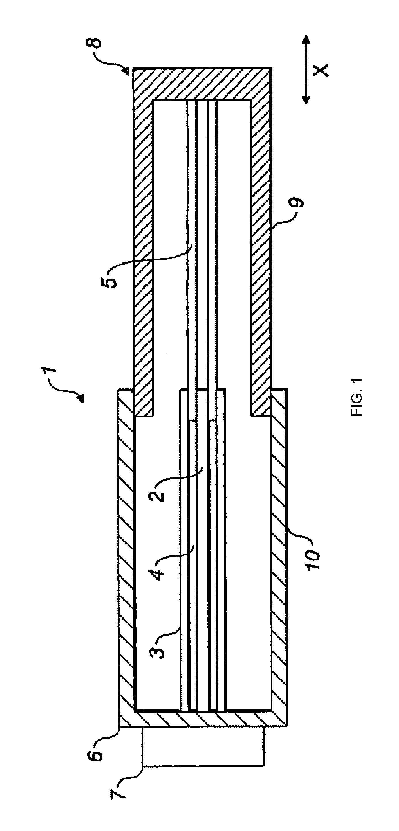
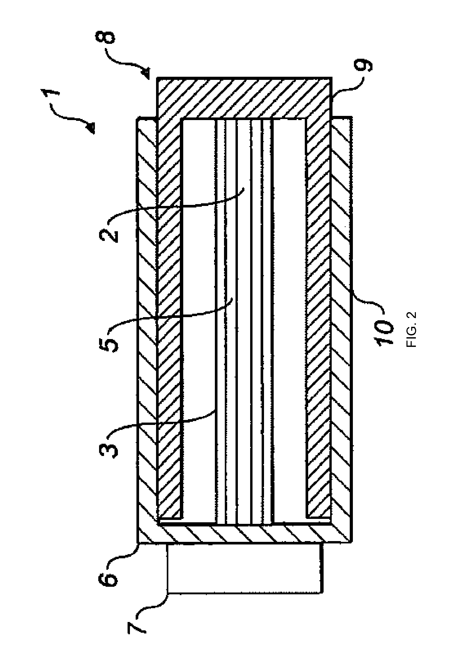
[0026]Turning firstly to FIG. 1, the linear capacitance displacement transducer 1 includes a first capacitor plate 2 and a second capacitor plate 3 defining a space 4 between the first and second capacitor plates 2,3. The displacement transducer 1 further includes a dielectric structure 5 movable longitudinally within the space 4 in the direction of arrows X. The first and second capacitor plates 2,3 are electrically and physically connected to a printed circuit board or similar layer 6 having a semiconductor integrated circuit 7, such as AD7746, mounted thereon. The dielectric structure 5 is operatively coupled to a movable element 8. The movable element 8 is connected to guide means 9 cooperating with guide means 10 extending from the printed circuit board 6.

[0027]In the preferred embodiment shown in FIG. 1 the first capacitor plate 2 is a solid right circular cylinder disposed coaxially and concentrically with a hollow right circular cylinder of the second capacitor plate 3. It w...


PUM


Abstract

A linear capacitance displacement transducer (1) comprising first (2) and second (3) fixed capacitor plate and a dielectric structure (5) moveable longitudinally within a space (4) between the first (2) and second (3) capacitor plates, the dielectric structure (5) being operatively coupled to a moveable element (8). The capacitor plates and the dielectric material may be cylindrical and disposed coaxially and concentrically. The transducer (1) enables a displacement sensor that is capable of monitoring liquid levels in a syringe type drug reservoir (101) with sufficient sensitivity as to allow detection of erroneous drug delivery. The sensor is inexpensive to manufacture and provides reliable performance through robust design.

Description

RELATED APPLICATION[0001]This application is a continuation of International Application No. PCT / GB2009 / 002353, which designated the United States and was filed on Oct. 2, 2009, which claims priority under 35 U.S.C. §119 or 365 to United Kingdom Application No. 0818077.0, filed on Oct. 2, 2008. The entire teachings of the above applications are incorporated herein by reference.FIELD OF THE INVENTION[0002]In devices for the programmed delivery of therapeutic products into the human or animal body, there is generally provided a pressurised reservoir of therapeutic product working in cooperation with a pumping chamber and valve means. The therapeutic product is typically pumped by the device through a tube to a cannula that pierces the patient's skin. The device can be capable of providing a variable rate of infusion of the therapeutic product to the patient over several days. This invention is directed to an improved displacement sensor for the pressurised reservoir.BACKGROUND TO THE ...

Claims


Application Information

Patent Timeline
IPC IPC(8): G01R27/04
CPCA61M5/14224A61M5/16809G01F11/029A61M5/16886G01D5/2405A61M5/1684A61M2205/3317A61M2205/3389A61M5/1452F15B15/2815G01B7/02
Inventor CEFAI, JOSEPH JOHNSHAPLEY, JULIANTHOMAS, NEILPOWELL, MATTHEWJONES, MARK STEPHEN
Owner INSULET NETHERLANDS BV
Why Eureka
Try Eureka