

Treatment planning system, device for calculating a scanning path and particle therapy system
a treatment planning system and scanning path technology, applied in the field of treatment planning system, can solve the problems of difficult to arbitrarily set the scanning direction of ion beams, the existing treatment planning system and the device for calculating the scanning path do not provide any means by which the operator can operate, and achieve the effect of improving uniformity and high uniformity in the irradiation target area
- Summary
- Abstract
- Description
- Claims
- Application Information
AI Technical Summary
Benefits of technology
Problems solved by technology
Method used
Image

Examples
first embodiment
[0030]A treatment planning system (or a scanning path creation system) according to a preferred embodiment of the present invention will be described below with reference to drawings. First, a particle therapy system for which the treatment planning system is used will be described with reference to FIGS. 3 and 4.
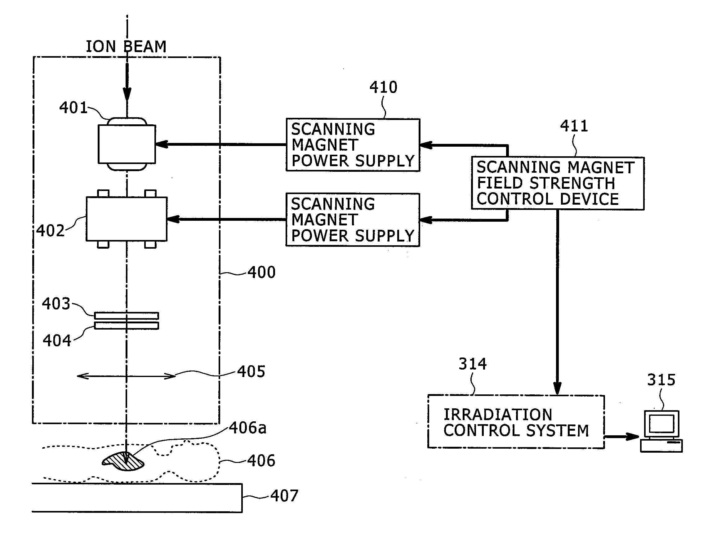
[0031]FIG. 3 shows an overall structure of the particle therapy system. An ion beam generator 301 includes an ion source 302, a preaccelerator 303, and an ion beam accelerator 304. Even though the ion beam accelerator of the present embodiment is assumed to be a synchrotron-type ion beam accelerator, the present embodiment is also applicable to other types of ion beam accelerators including cyclotron-type accelerators. The synchrotron-type ion beam accelerator 304 includes, as shown in FIG. 3, a bending magnet 305, an accelerator 306, an extraction radiofrequency device 307, an extraction deflector 308, and a quadruple magnet (not shown) which are arranged along the beam or...
second embodiment
[0067]Even though, in the first embodiment, the direction of target movement is extracted using 4DCT images, effects similar to those of the first embodiment can also be obtained according to a second embodiment of the invention by having the direction of target movement directly specified by the operator using ordinary CT data without using any 4DCT image. The second embodiment will be described below.
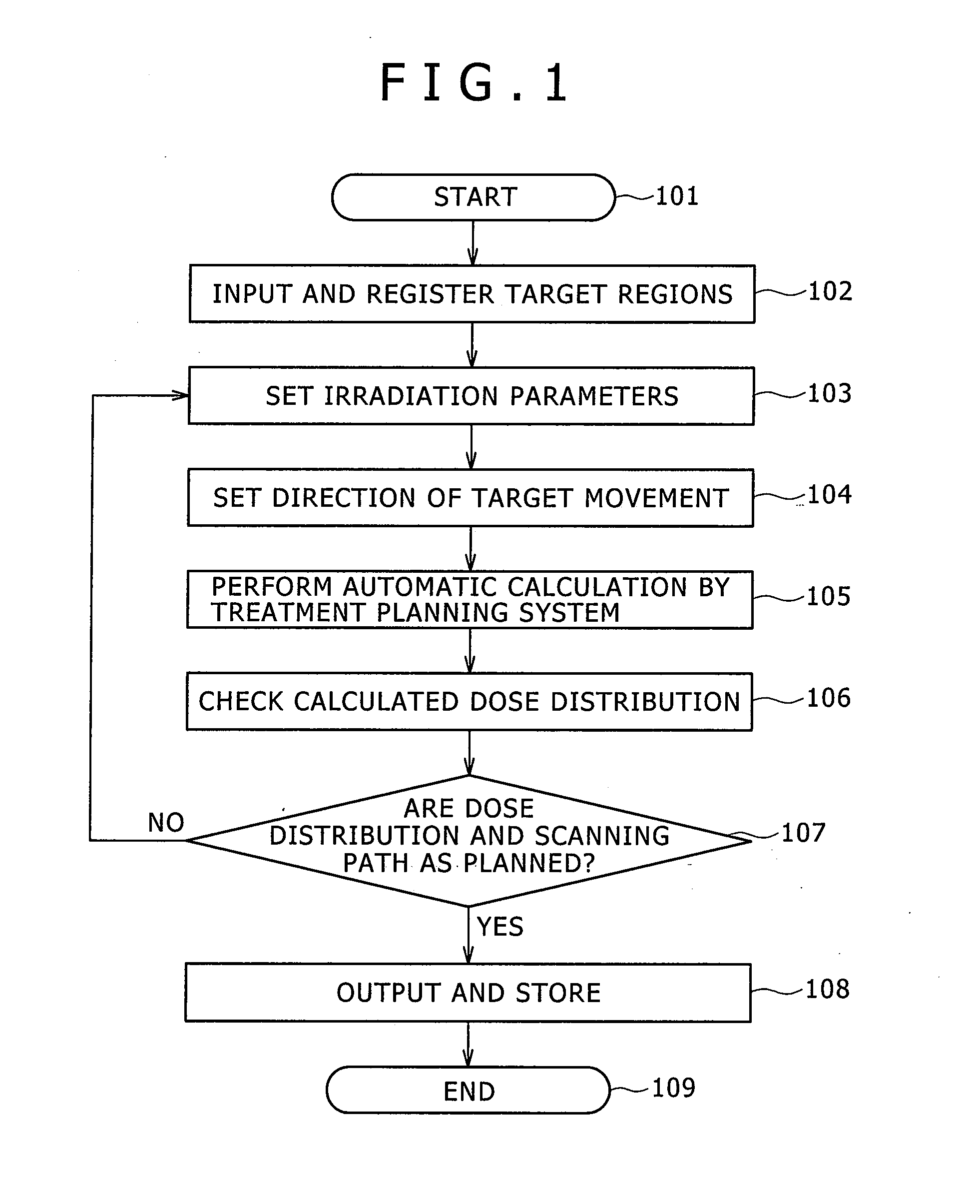
[0068]The operation according to the second embodiment is the same as in the first embodiment up to step 103 shown in FIG. 1. The operation differing from the first embodiment will be described in the following. In the second embodiment, the direction of target movement is determined, in step 104, by the operator without using any 4DCT data. In cases where the direction of movement of a specific organ caused, for example, by respiration or heart beat is not considered to vary much, the operator may directly specify the direction of target movement without checking the target position,...
third embodiment
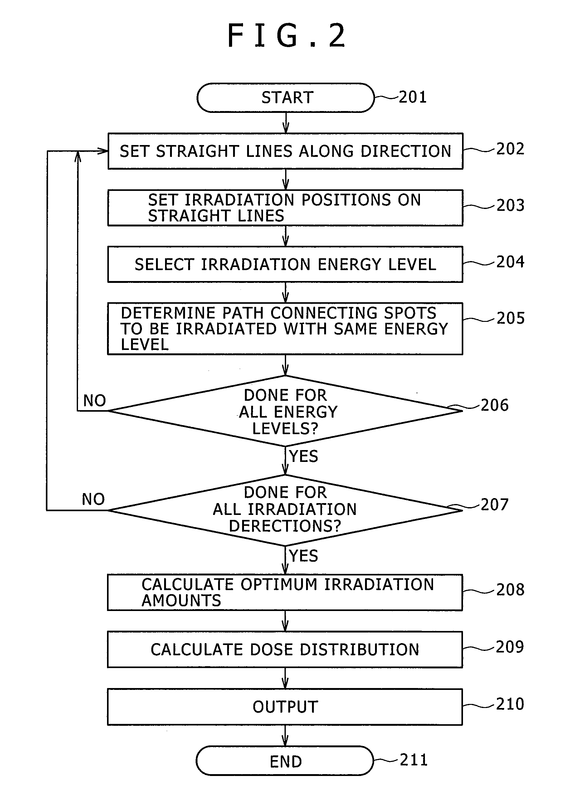
[0072]In the first and second embodiments, spots are arranged on straight lines parallel with a specified direction. In that way, when the specified direction is changed, the spot positions are also changed making it necessary to perform the operations beginning with step 203 shown in FIG. 2.
[0073]When a discrete scanning method in which ion beam irradiation is stopped during scanning is used, the dose distribution is not dependent on the scanning path as long as the spot positions remain unchanged. In this case, it is possible, unlike in the first and second embodiments, to change only the scanning path portion that begins at a predetermined spot into an arbitrary direction. Such a method will be described below as a third embodiment.
[0074]FIG. 15 shows the flow of operation, according to the third embodiment, corresponding to the automatic calculation performed by the treatment planning system 501 (step 105 shown in FIG. 1). After automatic calculation is started (step 1501), spot...
PUM
 Abstract
Description
Claims
Application Information