System and method for sweeping mirror enhanced imaging flow cytometry

Inactive Publication Date: 2012-01-05
FLUID IMAGING TECH
View PDF16 Cites 21 Cited by
  • Summary
  • Abstract
  • Description
  • Claims
  • Application Information

AI Technical Summary

Benefits of technology

[0005]It is an object of the present invention to provide an imaging flow cytometry system and method with improved sample fluid flow rate. It is also an object of the present invention to provide such an improved flow rate imaging flow cytometer system and method that may be incorporated into, or used with, existing imaging flow cytometers and provide better images with reduced blurring. These and other objects are achieved with the present invention, which enables imaging of higher than conventional sample flow rates through introduction of a tracking mirror, wherein the movement of the mirror is associated with the fluid flow rate. In other words, the tracking mirror is configured to track particles passing in the fluid at a known flow rate. In one embodiment, the imaging flow cytometry system and method of the present invention includes a scanning galvanometer mirror, a galvanometer driver circuit, one or more high current power supplies, a modification of an imaging flow cytometer's digital signal processor, and ramp

Problems solved by technology

The inefficiencies of standard methods of optically imaging with a very short flash, an objective lens and a CCD camera include using a very slow sam

Method used


Image

  • System and method for sweeping mirror enhanced imaging flow cytometry
  • System and method for sweeping mirror enhanced imaging flow cytometry
  • System and method for sweeping mirror enhanced imaging flow cytometry

Examples


Embodiment Construction

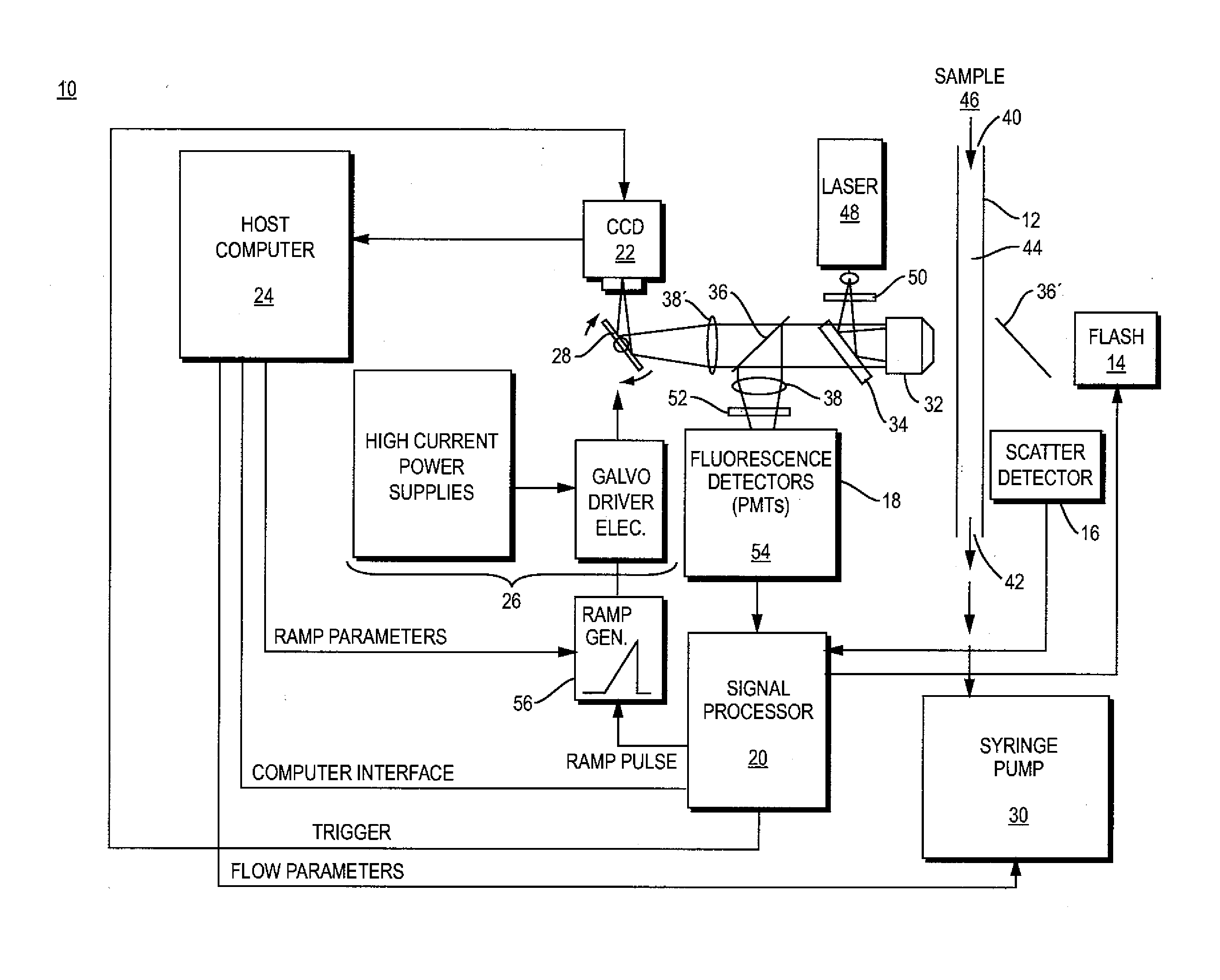
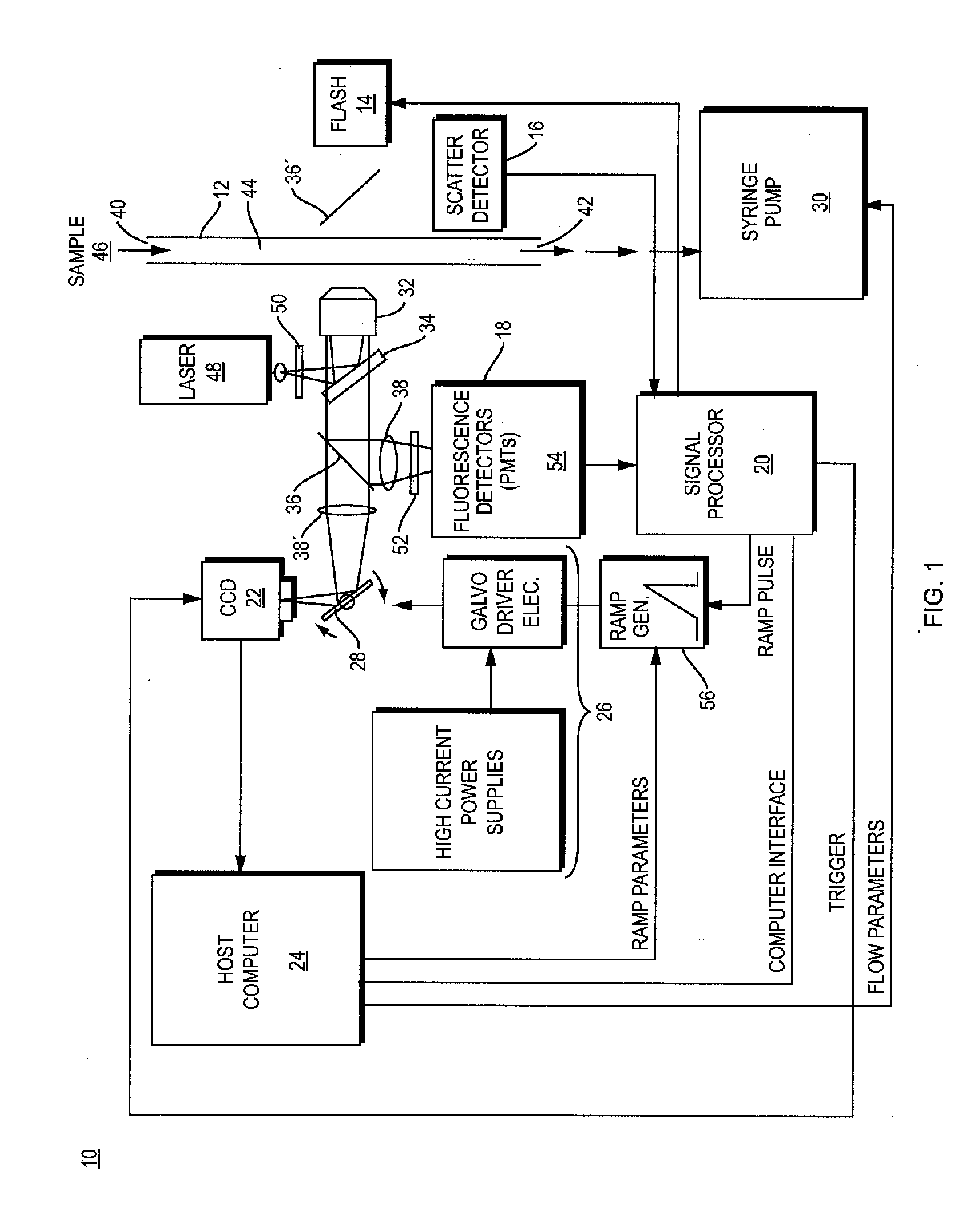
[0019]One embodiment of a system 10 of the present invention suitable for high speed automated counting and / or imaging of particles in a fluid is shown in FIG. 1. The system 10 includes a flow chamber 12, a backlighting generator 14, particle scatter and fluorescence detectors 16, 18, a signal processor 20, an image capturing system 22, a computing device 24, a scan generator circuit 26 including high current power supplies and galvanometer driver electronics to control programmable ramp generator 56, a scanning galvanometer and mirror combination 28, and a pump 30 capable of delivering a controllable fluid flow rate. The embodiment of the system 10 depicted in FIG. 1 also includes imaging and analysis optics such as the microscope objective 32, dichroic mirror 34, partial mirrors 36, 36′, and lenses 38 and 38′, although other configurations are possible. The combination of the components of the system 10 arranged and configured as described herein enable a user to detect and image ...


PUM


Abstract

An imaging flow cytometry system and method which includes a flow chamber, tracking mirror, microscope and imaging optics, image capturing system, device to regulate fluid flow through the chamber, and backlighting generator. The tracking mirror moves at a rate matched to the particle velocity in the flow chamber so as to enhance the sample flow rates possible with the system while maintaining clear and accurate imaging. The backlighting generator passes through the flow chamber and the objective before being focused on the image capturing system. Detected scatter events initiate tracking by the mirror, resulting in imaging with reduced motion blur even at high rates of flow.

Description

FIELD OF THE INVENTION[0001]The present invention relates generally to an optical flow imaging and analysis configuration used in particle analysis instrumentation, and more particularly to an optical flow imaging system and method incorporating a flow chamber and a tracking mirror which sweeps at a rate which is matched to the fluid flow rate, enabling accurate imaging at flow rates much faster than previously enabled.BACKGROUND OF THE INVENTION[0002]Various optical / flow systems employed for transporting a fluid within an analytical instrument to an imaging and optical analysis area exist in the art. A liquid sample is typically delivered into the bore of a flow chamber and the sample is interrogated in some way so as to generate analytical information concerning the nature or properties of the sample. For example, a laser beam may excite the sample present in the bore of the flow cell, and the emitted fluorescence energy provides signal information about the nature of the sample.[...

Claims


Application Information

Patent Timeline
IPC IPC(8): H04N7/18
CPCG01N15/1434G01N15/1463G01N21/6456
Inventor SIERACKI, CHRISTIAN K.ELLIS, SCOTT N.PETERSON, KENT A.
Owner FLUID IMAGING TECH
Why Eureka
Try Eureka