
Integrated diesel particulate filter and electric load bank

a technology of integrated diesel and electric load bank, which is applied in the direction of machines/engines, electric supply techniques, separation processes, etc., can solve the problems of engine harm, add to the cost and complexity of exhaust treatment systems required to comply with environmental regulations, etc., and achieve safe dissipation of excess electrical energy, prevent damage, and avoid overheating damage to electrical motor

Inactive Publication Date: 2012-01-05
RYPOS
View PDF23 Cites 30 Cited by
  • Summary
  • Abstract
  • Description
  • Claims
  • Application Information

AI Technical Summary

Benefits of technology

[0011]It is therefore an object of the present invention to provide an emissions control device that can remove particulate matter from combustion exhaust gases.
[0012]A further object of the present invention is to provide an emissions control device that can sufficiently load the output of an electrical power system (EPS) to prevent harm to the EPS engine during EPS operation at low or no service load.
[0013]Yet another object of the present invention is to provide an emissions control device that can safely dissipate excess electrical energy created by an electrical motor under no-load and braking conditions to avoid overheating damage to the electrical motor.

Problems solved by technology

The need to use several such devices in combination adds to the cost and complexity of the exhaust treatment systems required to comply with environmental regulations.
According to engine manufacturers, operating a diesel engine only at loads less than 10% to 50% of rated load causes harm to the engine.

Method used


Image

  • Integrated diesel particulate filter and electric load bank
  • Integrated diesel particulate filter and electric load bank
  • Integrated diesel particulate filter and electric load bank

Examples


Embodiment Construction

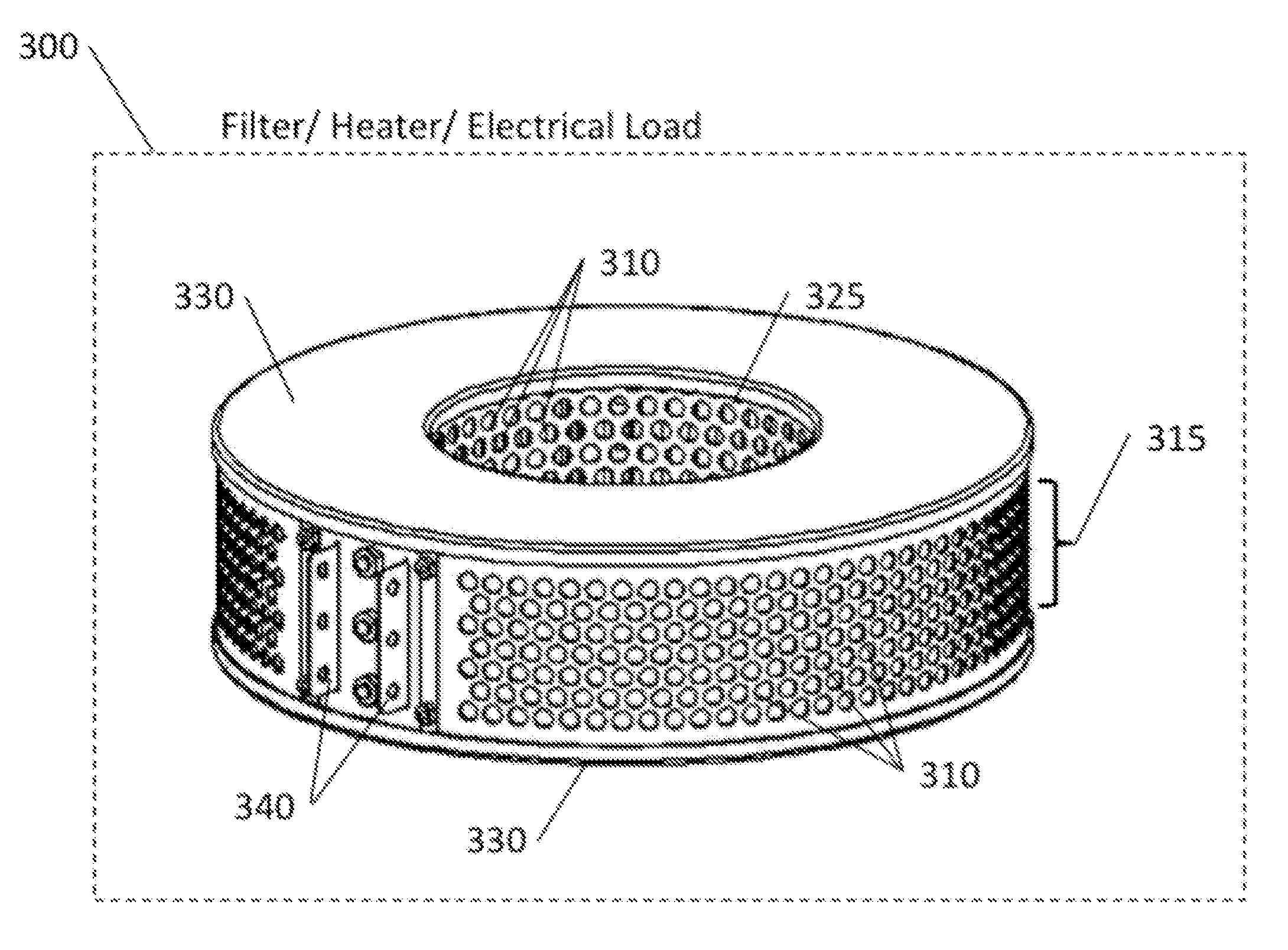
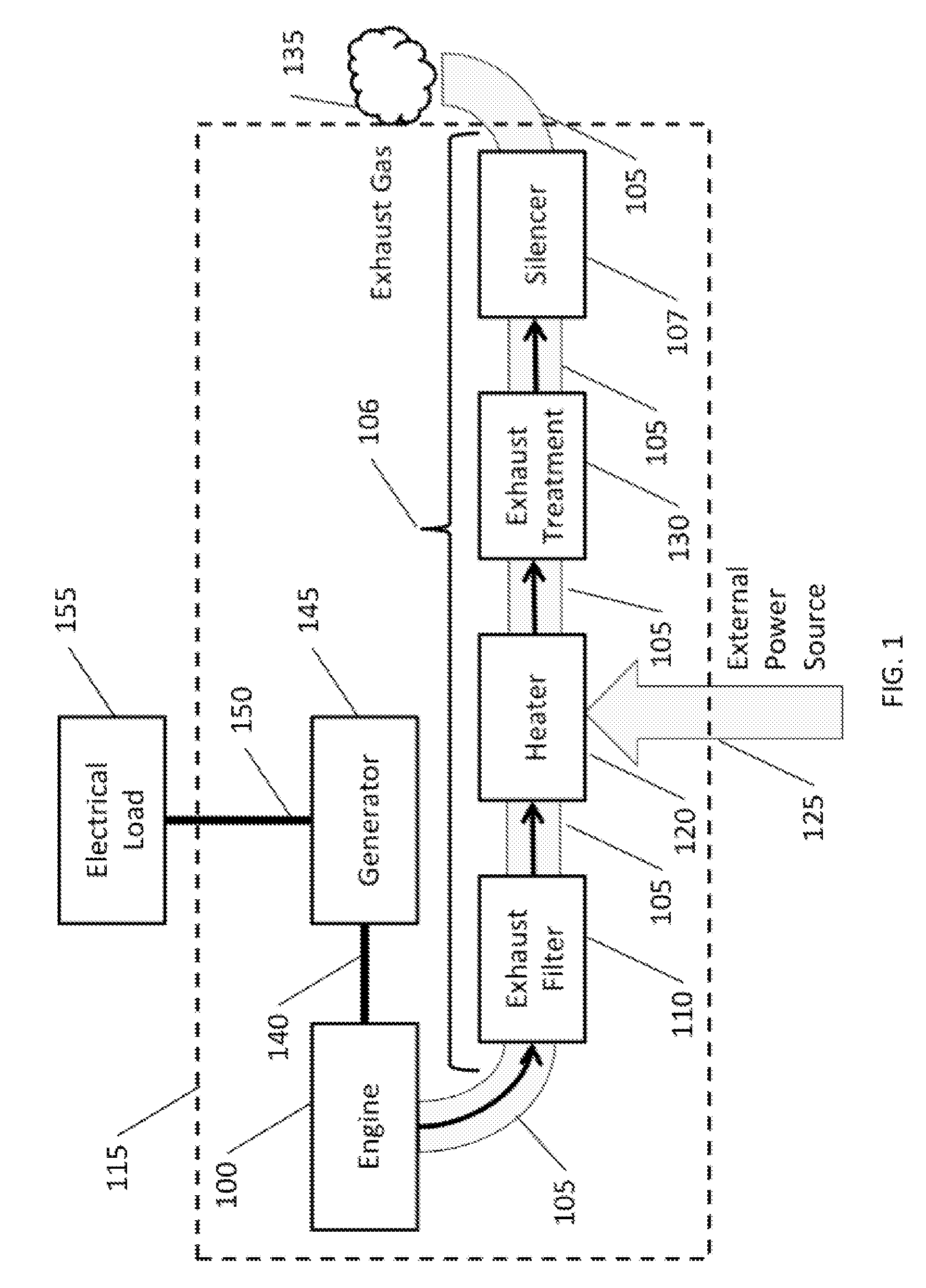
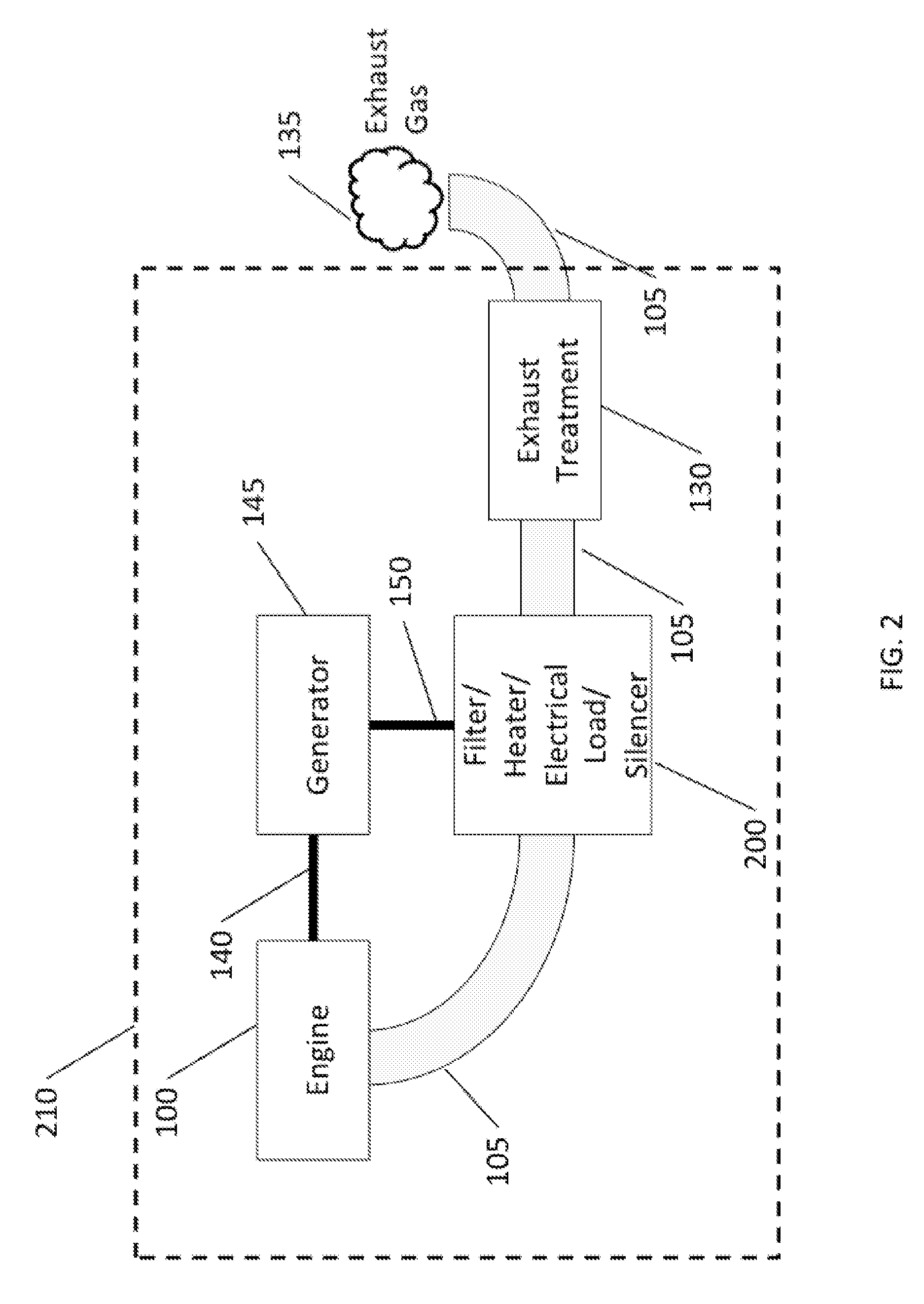
[0028]Referring to FIG. 1, the normal operation of an exemplary internal combustion engine 100 creates exhaust gas 135 that contains harmful pollutants including, but not limited to, particulate matter (PM), hydrocarbons (HC), nitrogen oxides (NOx), carbon monoxide (CO), engine lubricating oil, and unburned fuel. To reduce the dangers of exhaust gas 135 to human health, the United States Environmental Protection Agency (EPA) and state agencies regulate the pollutants emitted by the internal combustion engine 100. To comply with EPA and state environmental regulations, the manufacturer or operator of an internal combustion engine 100 may, for example, be required to install in the exhaust flow path 106 an exhaust filter 110 to remove particulate matter and an auxiliary exhaust treatment device 130 to remove gaseous pollutants from the exhaust gas. In some applications a heater 120 is required to ensure that the temperature of the exhaust gas 135 is sufficient for the auxiliary exhaus...


PUM

PropertyMeasurementUnit
Temperatureaaaaaaaaaa
Pressureaaaaaaaaaa
Electrical conductivityaaaaaaaaaa

Abstract

An apparatus for dissipating energy into the exhaust gas of an internal combustion engine includes a container for confining a flow path for exhaust gas from an internal combustion engine where the container has an inlet and an outlet. A porous, electrically conductive mesh is placed in the container such that exhaust gas can flow through the conductive mesh. At least two electrical terminals are in permanent electrical contact with the conductive mesh. An electrical power supply completes an electrical circuit through the conductive mesh with the power supply having two or more electrical outputs electrically connected to an equal number of electrical terminals on the conductive mesh. The apparatus provides a filter, heater, electrical load and silencer.

Description

CROSS REFERENCE TO RELATED APPLICATION[0001]This application is related to and claims priority from earlier filed provisional patent application 61 / 360,655, filed Jul. 1, 2010, and U.S. Provisional Application No. 61 / 364,862, filed Jul. 16, 2010, the entire contents thereof are incorporated herein by reference.BACKGROUND OF THE INVENTION[0002]The present disclosure relates to an electrically cleaned or maintained emissions control device, and specifically to a regenerable filter construction for removing particulate matter (PM) from combustion exhaust gases. Further, the present disclosure relates to electric load banks for Electric Power Systems (EPS).[0003]Federal and state environmental laws and regulations require that certain harmful substances, including PM and gaseous pollutants, be removed from the exhaust of internal combustion engines. States and localities also limit the noise emitted by the engines. To achieve the required reduction of both pollution and noise, the exhau...

Claims


Application Information

Patent Timeline
IPC IPC(8): B01D53/92B01D53/94B03C3/68B01D53/56B03C3/04B03C3/38
CPCB01D46/002B01D46/0023B01D46/0063B01D46/2411F01N2330/14F01N3/0226F01N3/027F01N3/0275F01N2330/10B01D46/521Y02A50/20B01D46/84B01D46/62B01D46/58
Inventor IBRAHIM, OSAMAPETER, KLAUSLOREN, NOAHWILLEY, PETERNARDI, ZACHARY L.SAEID, AMINSWENSON, JOHNMCDONALD, JAMES
Owner RYPOS
Learn More