Apparatus and method for treating etching solution

a technology of etching solution and apparatus, which is applied in the direction of reverse osmosis, membranes, and the nature of treatment water, can solve the problems of significant difficulty in concentration control, and achieve the effects of reducing the exchange frequency of etching solution, reducing the amount of acid used to neutralize a highly concentrated waste alkali solution, and efficient separation

Inactive Publication Date: 2012-01-12
KURITA WATER INDUSTRIES LTD
View PDF17 Cites 16 Cited by
  • Summary
  • Abstract
  • Description
  • Claims
  • Application Information

AI Technical Summary

Benefits of technology

[0022]The apparatus and method for treating an etching solution of the present invention remove an etching solution containing silicon components and / or dopants eluted from silicon by a membrane separation treatment, and circulate the etching solution to the etching bath, which allows the etching solution to be used for a longer period of time than conventional art and reduces the exchange frequencies of the etching solution.
[0023]That is, with the present invention, silicate ions and dopant ions which affect the etching rate can be separated efficiently, so an etching solution can be used without having to replace it for a long time. Moreover, since the etching solution does not need to be replaced for a longer time than conventional art, the amount of acid used to neutralize a highly concentrated waste alkali solution can be reduced.
[0024]The membrane separation means may be provided with a nanofiltration membrane which selectively removes multivalent ions having a valence of two or more. In this case, multivalent ions having a valence of two or more, for example, silicate ions (e.g., SiO32−), in the etching solution may be selectively separated while keeping the alkalinity of the etching solution, so the processing time for the texturing process may be stabilized and reduced.
[0025]The membrane separation means may be provided with a nanofiltration membrane which removes multivalent ions having a valence of two or more, alkali metal ions having a valence of one, and hydroxide ions. In this case, the etching solution which does not permeate the membrane separation means is alkaline, so silicic acid is ionized and fouling of the nanofiltration membrane can be prevented.
[0026]That is, under a neutral condition, silicate ions solate and reduce flux of the nanofiltration membrane, but by keeping the etching solution which does not permeate the membrane alkaline, solation of silicate ions can be prevented and thus fouling of the nanofiltration membrane can be prevented.
[0027]The membrane separation means may be provided with a nanofiltration membrane and an ultrafiltration membrane which is installed at an upstream side of the nanofiltration membrane. The etching solution may contain high molecular weight material produced by reactions of dopants, organic substances, silicate ions or the like. So, when the etching solution is directly supplied to the nanofiltration membrane, the high molecular weight material may deposit on the surface of the membrane and reduce the flux thereof. By installing the ultrafiltration membrane module at an upstream side of the nanofiltration membrane module for removing the high molecular weight material, fouling of the nanofiltration membrane can be prevented.

Problems solved by technology

Since the water temperature in the etching bath is around 80° C., water readily evaporates and the NaOH concentration rises, which makes concentration control significantly difficult.

Method used


Image

  • Apparatus and method for treating etching solution
  • Apparatus and method for treating etching solution
  • Apparatus and method for treating etching solution

Examples


example 1

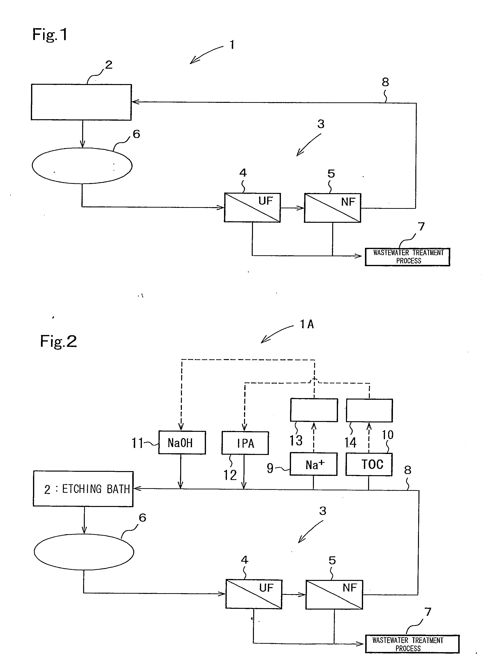
[0083]An apparatus shown in FIG. 1 was used as the apparatus for treating etching solution. The volume of the etching bath 2 was the same as that of COMPARATIVE EXAMPLE 1, and specifications and operation conditions of the UF membrane module 4 and NF membrane module 5 were as stated below.

[0084]UF Membrane Module 4: Nitto Denko Corp., “NTU-3306-K6R”

[0085]NF Membrane Module 5: NADIR Corp. (Germany), “NPO30”

[0086]Amount of Water Introduced to UF Membrane Module 4: 58 L / min

[0087]Solution temperature (T1) of introduced solution (permeated solution of NF membrane module 5 and solution supplied through a Chiller (not illustrated in FIG. 1) after heat exchange treatment) to UF Membrane Module 4: 20° C.

[0088]Solution temperature (T2) of returned solution (solution supplied from the circulation means 6 and solution supplied through a heater (not illustrated in FIG. 1) after heat exchange treatment) to etching bath 2: 80° C.

[0089]An etching solution in the etching bath 2 was the contaminated ...

example 2

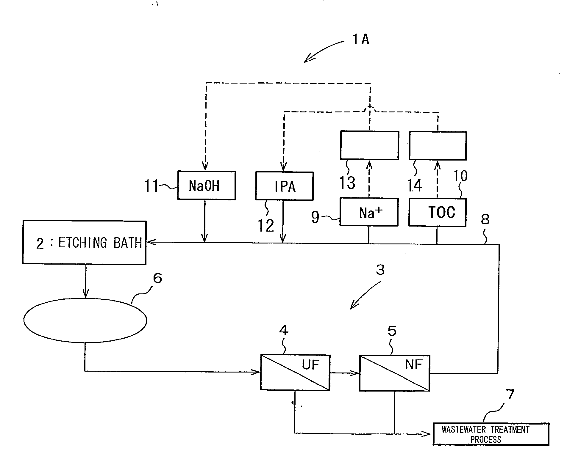
[0093]As the apparatus for treating etching solution, the apparatus as shown in FIG. 2 provided with alkaline (NaOH in the EXAMPLE) adding means and organic additive (IPA in the EXAMPLE) adding means was used. All other conditions for the etching treatment were the same as those in EXAMPLE 1.

[0094]As alkali concentration measuring means 9, a pH meter was used. A NaOH solution (24%) was added with a chemical feeding pump so that the Na+ concentration after addition would be 31,400 mg / L.

[0095]As IPA concentration measuring means 10, a TOC meter was used. An IPA solution (20%) was added to the return pipe 8 with a chemical feeding pump so that the IPA concentration after addition would be 11,700 mg / L.

[0096]The composition of the etching solution (after 12 hours elapsed since the beginning of the operation) in the return pipe 8 downstream of the point where NaOH and IPA were added is shown in Table 2.

TABLE 2EXAMPLE 1Raw Water(Removal Rate %)EXAMPLE 2SiO2 (mg / L)226009500(58%)6500Na+ (mg / ...

example 4

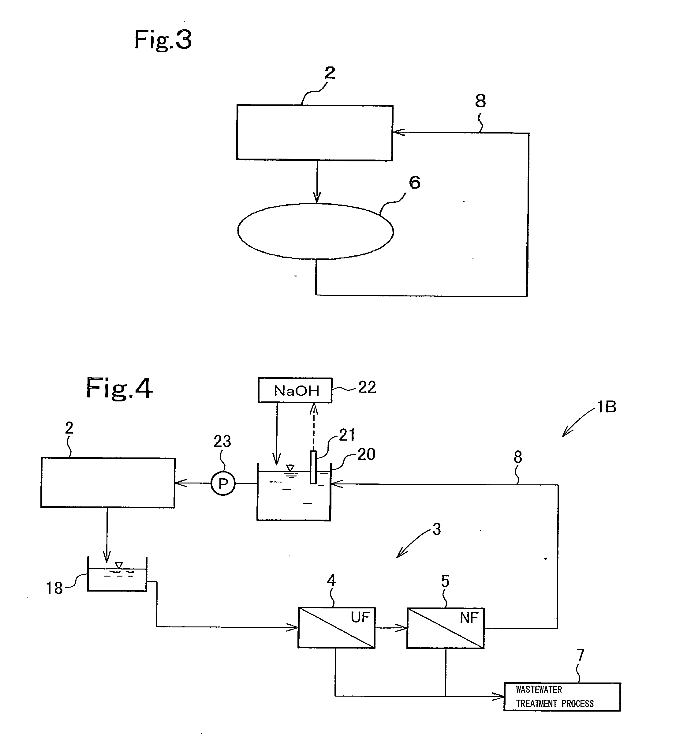
[0109]The apparatus shown in FIG. 4 was used for treating etching solution. The volume of the etching bath 2 was the same as that of COMPARATIVE EXAMPLE 2, and specifications and operation conditions of the UF membrane module 4 and NF membrane module 5 are stated below.

[0110]EXAMPLE 4 shows a result of a once-through treatment where the concentrated solution supplied from the membrane separation means 3 was not returned to the intermediary bath 18.

[0111]UF Membrane Module 4: Nitto Denko Corp., “NTU-3306-K6R”

[0112]NF Membrane Module 5: 2 8-Inch NF Membrane of Molecular Weight Cut Off 300 installed in a Series

[0113]Amount of water introduced to UF Membrane Module 4: 10 L / min

[0114]Water introduced to UF membrane module 4 was heat-exchanged with the permeated solution of NF membrane module 5 and then passed through a chiller (not illustrated in FIG. 4), and had a temperature of 50° C.

[0115]The returning water to the etching bath 2 was heat-exchanged with the solution from the intermedia...


PUM

PropertyMeasurementUnit
temperatureaaaaaaaaaa
pHaaaaaaaaaa
refractive indexaaaaaaaaaa

Abstract

An apparatus and method for treating an etching solution, where the replacement frequency of the etching solution is reduced, while the inclusion of impurities in the treated etching solution is prevented. An apparatus for treating an etching solution in order to reuse the etching solution used in etching treatment of silicon, where the apparatus includes: membrane separation means 3 which performs membrane separation treatment on the etching solution supplied from an etching bath 2; and circulating means 6 which circulates a permeated solution supplied from the membrane separation means 3 to the etching bath 2. The membrane separation means 3 includes a UF membrane module 4 and an NF membrane module 5. Alkaline and organic substances may be added to the etching solution supplied from the membrane separation means 3.

Description

FIELD OF INVENTION[0001]The present invention relates to an apparatus and a method for treating an etching solution, and in particular, the present invention relates to an apparatus and a method for treating an etching solution preferable in the case of, for example, forming a texture surface by etching a surface of a crystalline silicon substrate.BACKGROUND OF INVENTION[0002]In a crystalline silicon substrate used for a solar cell substrate, the surface of the substrate is made to have a fine pyramidal texture in order to improve the power generation efficiency by increasing the optical path length of incident light. Such a substrate can be obtained by etching (texture etching), a surface of a silicon substrate with an etching solution which may be, for example, a mixture solution of an alkaline solution containing 0.05 to 2 mol / L of NaOH or KOH, and a surfactant whose primary ingredient is caprylic acid or lauric acid of 0.01 mol / L or higher (Patent Document 1). The etching soluti...

Claims


Application Information

Patent Timeline
Patent Type & Authority Applications(United States)
IPC IPC(8): C23F1/46C02F11/12
CPCB01D61/027B01D61/12Y02E10/50H01L31/0236H01L21/30604C02F2103/346C02F2001/5218B01D61/145B01D61/22B01D61/58B01D2311/06C02F1/52C02F1/66C02F11/12B01D2311/12B01D2311/24B01D2311/18B01D2311/243B01D2311/10Y02W10/37H01L21/67075C02F11/148
Inventor KOMORI, HIDEYUKIORITA, NOBUHIRO
Owner KURITA WATER INDUSTRIES LTD
Why Eureka
Try Eureka