
Drive device for a wind turbine

Inactive Publication Date: 2012-01-12
SUZLON ENERGY GMBH (DE)
View PDF3 Cites 15 Cited by
  • Summary
  • Abstract
  • Description
  • Claims
  • Application Information

AI Technical Summary

Benefits of technology

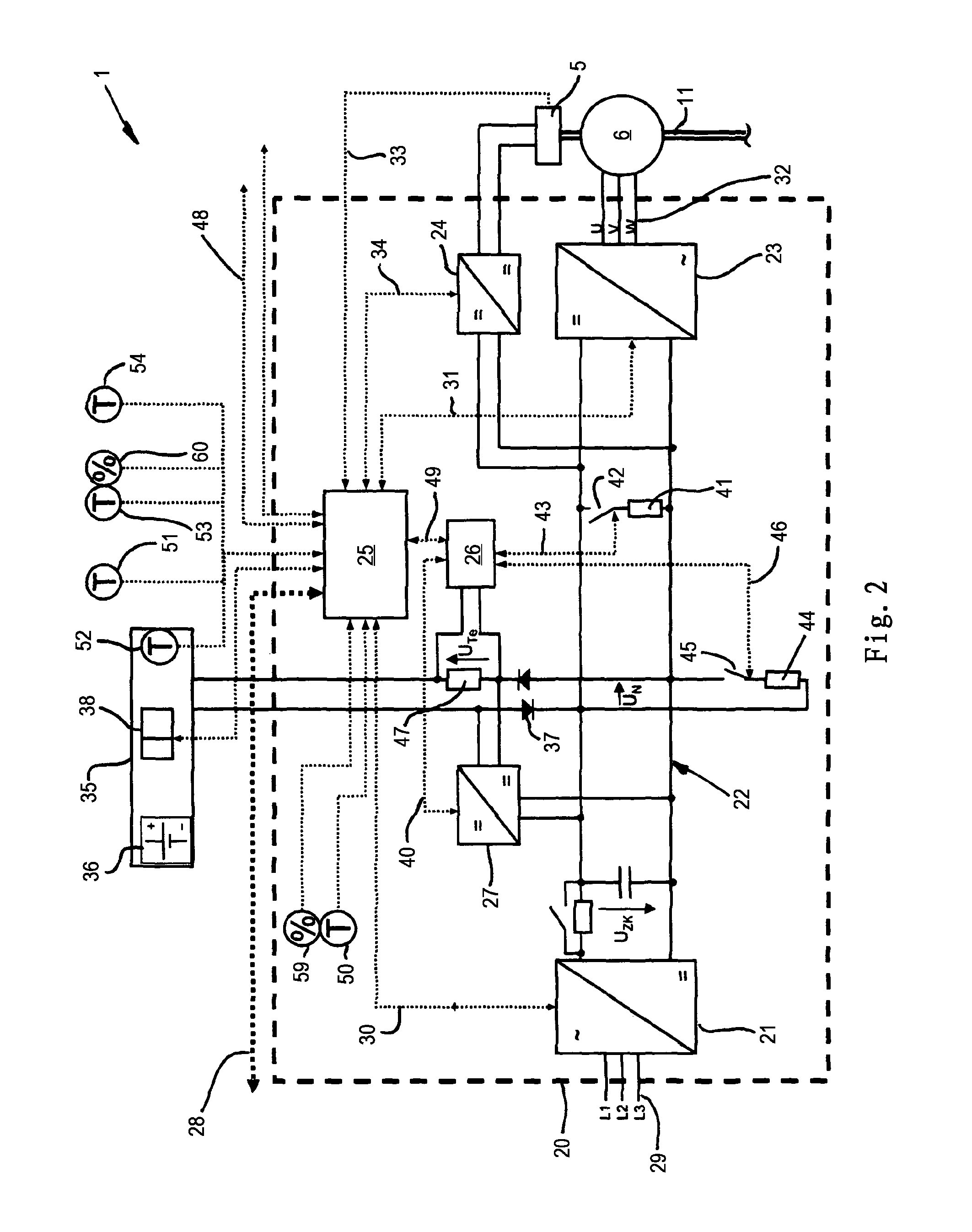
[0005]The problem is solved with the features of claim 1 according to the present invention, by providing a direct-voltage regulator which is connected with the intermediate circuit, via which the brake is electrically powered. By powering the brake via the intermediate circuit, an additional voltage source for the brake can be avoided and the brake can be implemented extremely simply.
[0009]A particular beneficial embodiment of the present invention is disclosed that a physical unitary inverter unit is provided, in which the supplying device, the direct-voltage regulator, the charging unit, the charging control system and the control unit are disposed. Thereby, the component complexity of the driving system is considerably reduced, whereby the cost of the production and the assembly and the error-proneness is also clearly reduced.

Problems solved by technology

Thus, a further voltage source for charging the emergency operation supplying device becomes redundant.

Method used


Image

  • Drive device for a wind turbine
  • Drive device for a wind turbine
  • Drive device for a wind turbine

Examples


Embodiment Construction

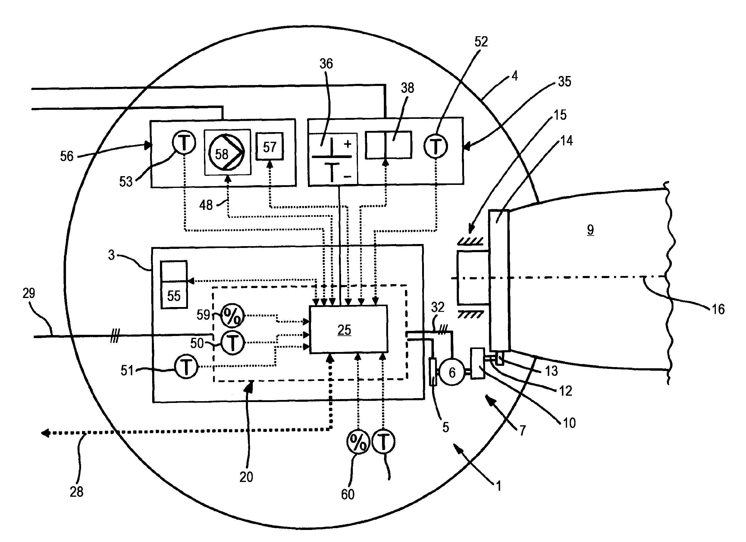
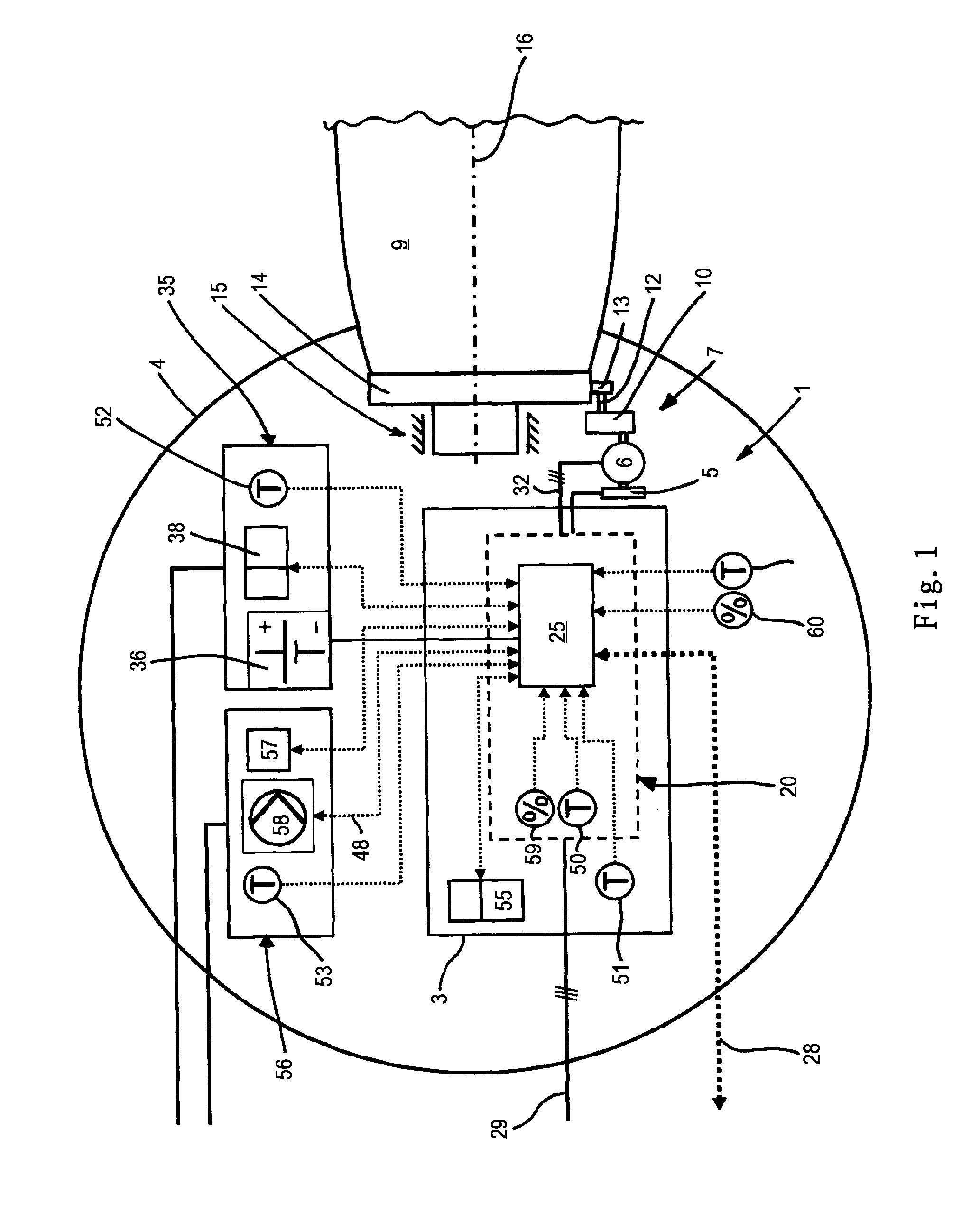
[0016]FIG. 1 shows an embodiment of the driving device 1 according to the present invention, wherein an inverter unit 20 is disposed in a switch cabinet 4 in a hub 3 of a not-shown wind turbine. The inverter unit 20 powers the asynchronous machine 6 of the driving unit 7 of the blade adjusting means of a rotor blade 9 via electrical connector 32. The driving unit 7 can have a gear 10, wherein the driving shaft 11 of the gear 10 is directly connected with the asynchronous machine 9 and the driven shaft 12 is connected with a pinion 13. The pinion 13 gears into a sprocket 14 which is torque-proof connected with the rotor blade 9, wherein the rotor blade 9 is mounted in the hub 4 via a blade bearing 15 and is rotatable around its longitudinal axis.

[0017]FIG. 2 shows the inverter unit 20 of the driving system 1 schematically. Here, the asynchronous machine 6 is connected with a supply network 10 via an electrical supplying device 2. The inverter unit 20 comprises the electrical supplyin...


PUM


Abstract

A driving device for a rotor blade of a wind turbine has an asynchronous machine (6) for adjusting the rotor blade, an electrically operable brake (5) disposed at the driving unit for fixing or braking the driving unit and an electrical supplying device (2), via which the asynchronous machine is connectable with a three-phase power supply network. The supplying device comprises a rectifier (21), an inverted rectifier (23) and a direct-voltage intermediate circuit. A direct-voltage regulator (24) is provided which is connected with the intermediate circuit, via which the brake is electrically supplied. By supplying the brake by the intermediate circuit, an additional voltage source for the brake can be spared and the brake can be implemented extremely simply.

Description

FIELD OF THE INVENTION[0001]The present invention relates to a driving device for a rotor blade of a wind turbine. Such wind turbine comprises a rotor with a hub, and the rotor is rotatably disposed at a machine room, wherein the rotor comprises at least one electromechanical driving device for adjusting the Angle Of Attack of at least one rotor blade which is fixable at the hub. This driving device comprises an asynchronous machine for adjusting the rotor blade, an electrically operable brake disposed at the driving unit, for fixing or braking the driving unit, and an electrical supplying device, via which the asynchronous machine is connectable with a three-phase power supply network. The supplying device comprises a rectifier, an inverted rectifier and a direct-voltage intermediate circuit. Usually, a dedicated driving device is provided for each rotor blade of a wind turbine. In case of emergency, such as failure of components or the voltage supply, an emergency operation supply...

Claims


Application Information

Patent Timeline
IPC IPC(8): F03D7/00
CPCF03D7/0224F03D11/00F05B2260/20F05B2260/76F05B2260/902Y02T50/675F05B2270/325Y02B10/30Y02E10/722Y02E10/723F05B2270/323F03D80/00Y02E10/72Y02T50/60F03D17/00F03D80/60F03D80/82
Inventor VILBRANDT, REINHARDLARITZ, CHRISTIANWILLAUSCHUS, OLAF
Owner SUZLON ENERGY GMBH (DE)
Learn More