

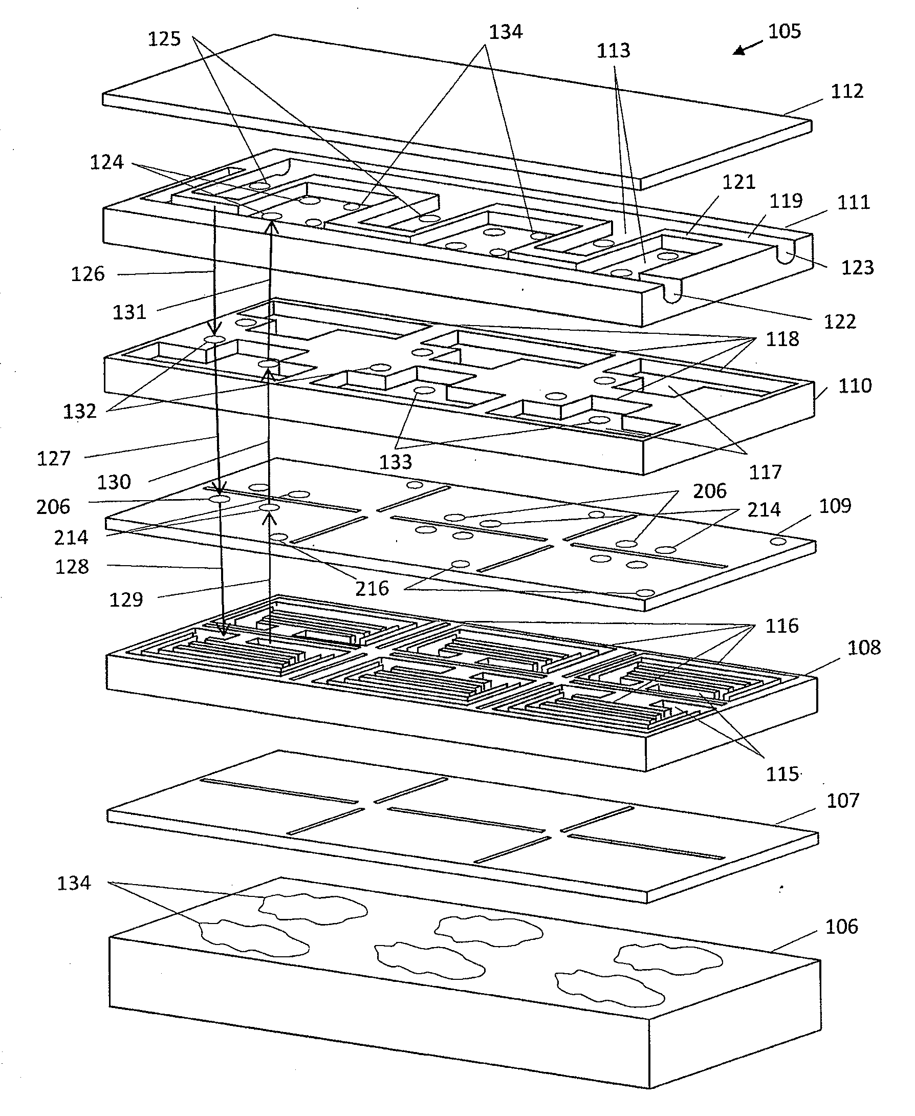
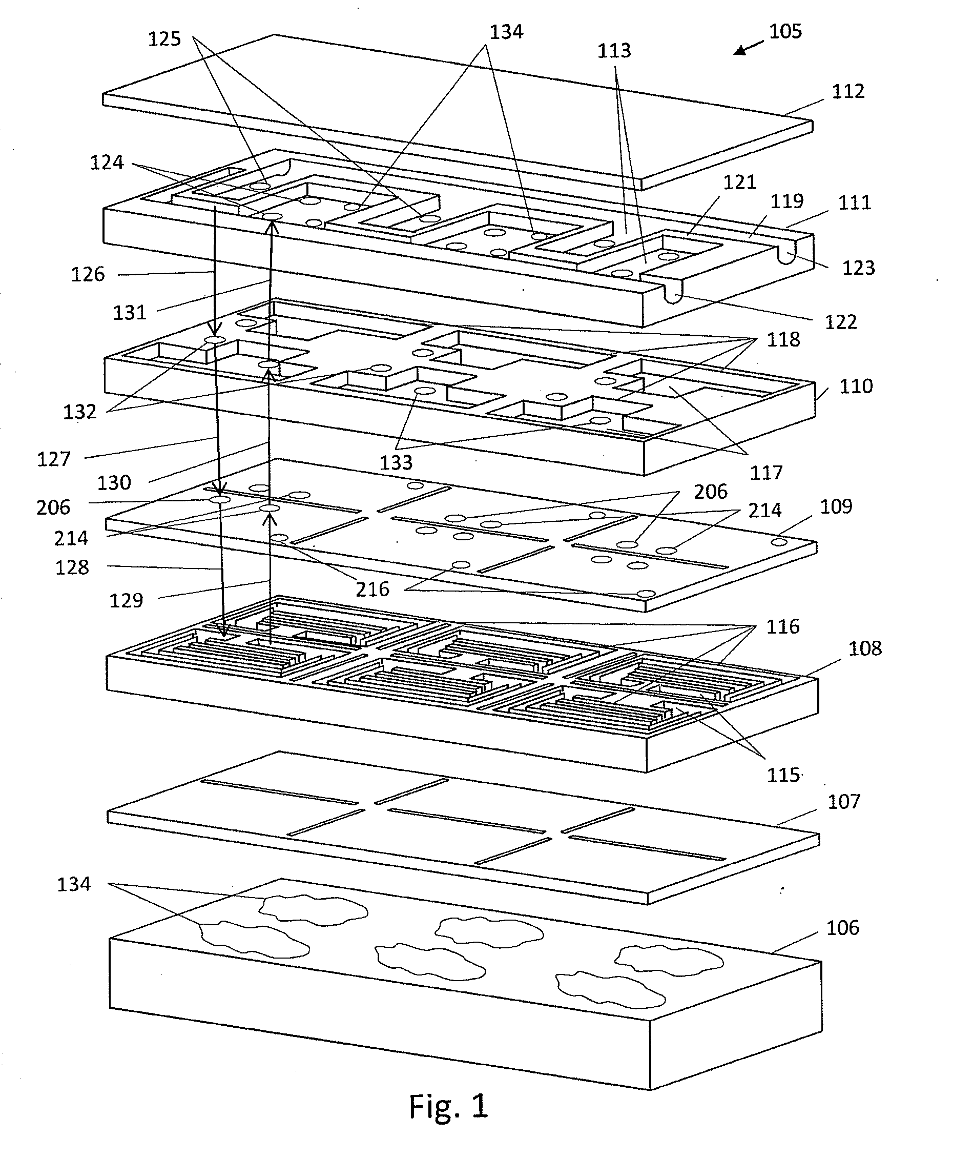
Proportional Micro-Valve With Thermal Feedback
a technology of proportional micro-valve and thermal feedback, which is applied in the direction of temperatue control, process and machine control, instruments, etc., can solve the problems of over-cooling and under-cooling of some portions of the computer chip, and the heat exchanger is not designed, so as to increase the risk of liquid cooling, the risk of damage to the computer components, and the manufacturing cos
- Summary
- Abstract
- Description
- Claims
- Application Information
AI Technical Summary
Benefits of technology
Problems solved by technology
Method used
Image

Examples
Embodiment Construction
[0033]Data centers and the multiplicity of types of data center equipment and electronic components located therein are well known in the art. It is also well known that electronic components within a data center generate a significant amount of heat that must be controlled by various means to maintain the data center equipment in working order. While it is not practical to include an exhaustive list of the function and type of every potential type of equipment that might be found in a data center of a business or other organization, for purposes of this disclosure, the term “electronic component” will be used to refer to any type of heat-generating component that one may find useful to locate within a protected environment of an organization's data center or other facility for the collection and installation of computer systems, electronics or controls. Such electronic components typically comprise, but are not limited to, computer systems, electronics, data storage systems, commun...
PUM
 Abstract
Description
Claims
Application Information