Power converting apparatus
a power converting apparatus and power technology, applied in the direction of power conversion systems, dc-dc conversion, climate sustainability, etc., can solve the problems of large loss and noise in the above-mentioned kind of power converting apparatus, and achieve the effects of low voltage, low cost, and improved input power factor
- Summary
- Abstract
- Description
- Claims
- Application Information
AI Technical Summary
Benefits of technology
Problems solved by technology
Method used
Image

Examples
first embodiment
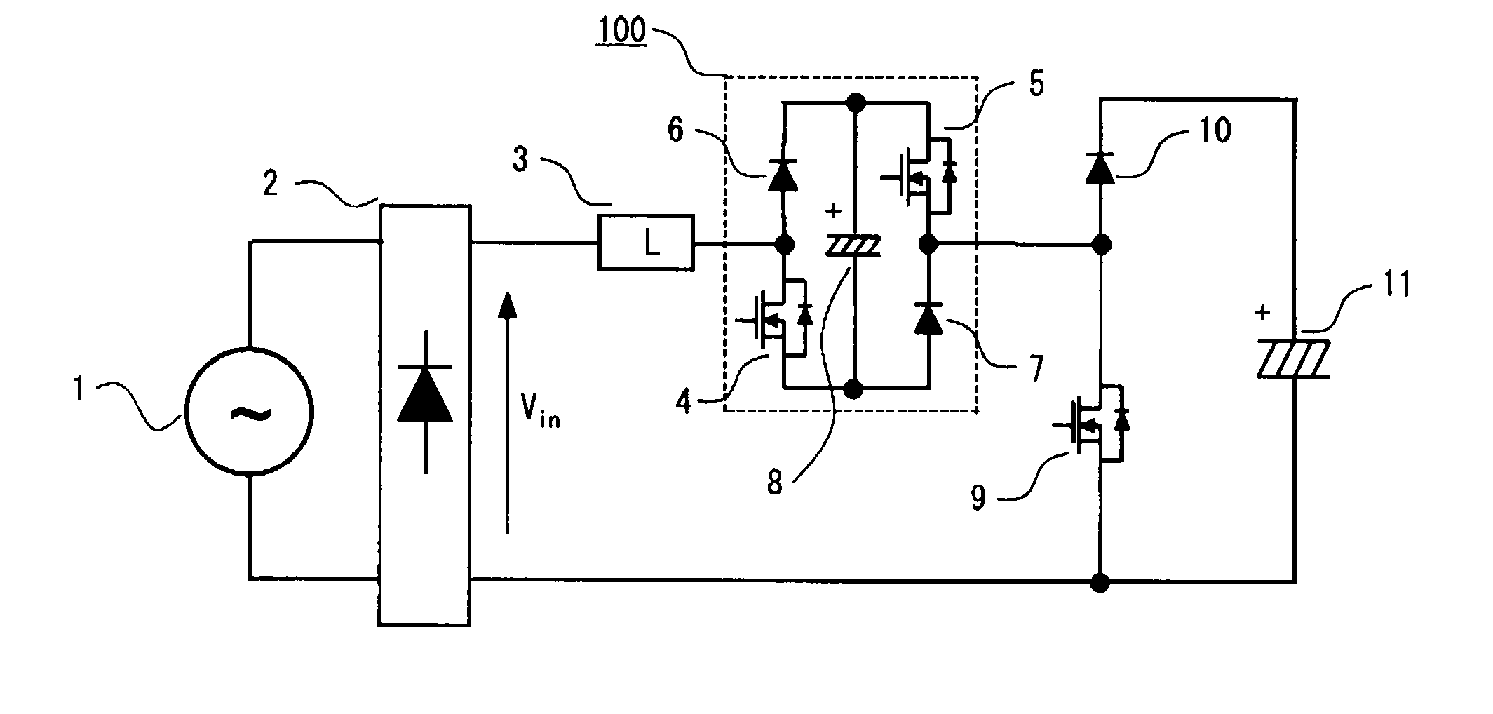
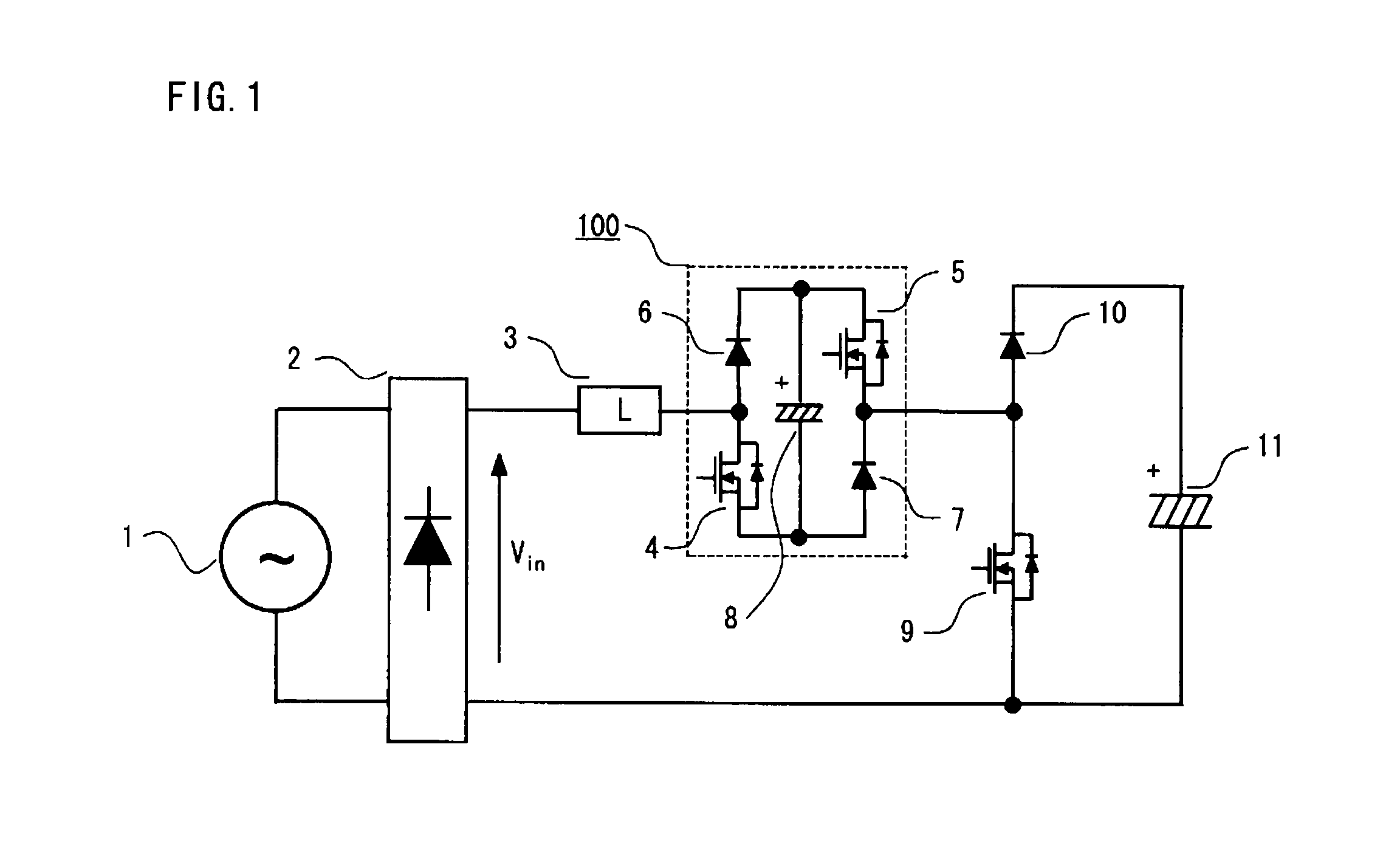
[0022]A power converting apparatus according to a first embodiment of this invention is now described below. FIG. 1 is a general configuration diagram of the power converting apparatus according to the first embodiment of the invention.
[0023]As depicted in FIG. 1, an AC voltage source 1 (hereinafter referred to simply as the AC power supply 1) which serves as an AC input power supply is connected to a diode bridge 2 which serves as a rectification circuit. An output of the diode bridge 2 is connected to a reactor 3 which serves as a current-limiting circuit and an AC side of an inverter circuit 100 configured with a single-phase inverter is series-connected to a downstream end of the reactor 3. The single-phase inverter constituting the inverter circuit 100 includes semiconductor switching devices 4, 5, diodes 6, 7 and a DC voltage source 8. An insulated-gate bipolar transistor (IGBT) in which diodes are connected in reverse parallel or a metal oxide semiconductor field effect trans...
second embodiment
[0054]Although one end of the short-circuiting switch 9 is connected to the AC output line of the inverter circuit 100 in the above-described first embodiment, one end of a short-circuiting switch 9a is connected to a negative electrode side of the DC voltage source 8 which forms part of the inverter circuit 100 in this second embodiment as illustrated in FIG. 8. The other end of the short-circuiting switch 9a is connected to the negative electrode side of the smoothing capacitor 11, or one end of the diode bridge 2, in the same fashion as in the foregoing first embodiment.
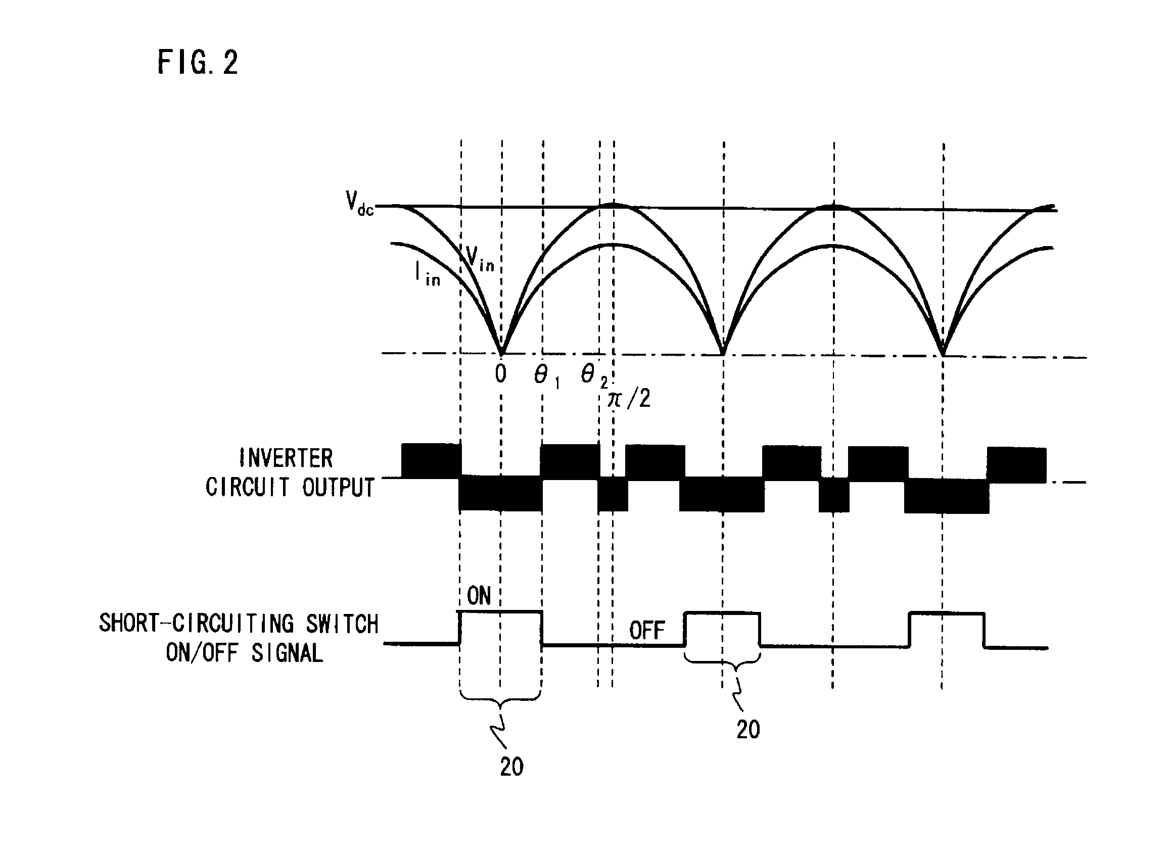
[0055]The inverter circuit 100 and the short-circuiting switch 9a are controlled in the same way as in the foregoing first embodiment. When the short-circuiting switch 9a is in the ON state, or when the phase θ of the input voltage from the AC power supply 1 falls within any of the short-circuiting phase ranges 20 of the zero-crossing phases (θ=0, π) ±θ1, however, there is formed a current path as indicated in FIG...
third embodiment
[0058]Next, a power converting apparatus according to a third embodiment of this invention is described with reference to FIG. 10.
[0059]As depicted in FIG. 10, an output from a first terminal of the AC power supply 1 is connected to the reactor 3 and an AC side of an inverter circuit 300 configured with a single-phase inverter is series-connected to a downstream end of the reactor 3. The single-phase inverter provided in the inverter circuit 300 includes semiconductor switching devices 4, 5, 16, 17 each of which is made up of an IGBT in which diodes are connected in reverse parallel or a MOSFET incorporating a diode connected between a source and a drain as well as a DC voltage source 8.
[0060]Also, a halfway point of a first series circuit 15a which constitutes an inverter in which a short-circuiting switch 12a made up of a semiconductor switching device and a rectifier diode 13a are connected in series is connected to an AC output line at a downstream end of the inverter circuit 30...
PUM
 Abstract
Description
Claims
Application Information
 - R&D
- Intellectual Property
- Life Sciences
- Materials
- Tech Scout
- Unparalleled Data Quality
- Higher Quality Content
- 60% Fewer Hallucinations
Browse by: Latest US Patents, China's latest patents, Technical Efficacy Thesaurus, Application Domain, Technology Topic, Popular Technical Reports.
© 2025 PatSnap. All rights reserved.Legal|Privacy policy|Modern Slavery Act Transparency Statement|Sitemap|About US| Contact US: help@patsnap.com