Packaged multicore fiber optical transceiver module

a multi-core fiber and optical transceiver technology, applied in the direction of optical elements, cladded optical fibres, instruments, etc., can solve the problems of inability to provide a practical interface with multi-core optical fibers, complex fabrication, time-consuming, etc., and achieve the effect of facilitating optical coupling

Inactive Publication Date: 2012-01-19
IBM CORP
View PDF9 Cites 52 Cited by
  • Summary
  • Abstract
  • Description
  • Claims
  • Application Information

AI Technical Summary

Benefits of technology

[0014]In a third exemplary aspect, also described herein is a method for coupling to a multicore optical fiber strand, including providing a multicore optical fiber strand comprising a plurality of optical cores and a cladding commonly shared by the plurality of optical cores, the multicore optical fiber not a Photonic Crystal Fiber (PCF), the optical cores being exposed at a surface of an end facet of the multicore optical fiber; providing a substrate, a surface of the substrate including a plurality of optoelectronic devices, arranged in a 2D array pattern that corresponds to a 2D array pattern corresponding to different light cores of the multicore optical fiber, wherein each optoelectronic device on the substrate surface provides one of a receive function and a transmit function for interacting with a corresponding core of the multicore optical fiber strand; and bringing the multicore optical fiber strand into sufficiently close proximity to the plurality of optoelectronic devices to facilitate an optical coupling.
[0015]Thus, the present invention provides an optical and electrical packaging approach for interfacing multicore fibers with optoelectronic arrays that is both practical and effective and permits interface for plurality of multicore fibers as an array of fibers.

Problems solved by technology

Some work, for example, by OFS Labs, has been done on building individual core breakout cables, but the fabrication may be quite complex and time consuming.
However, prior to the present invention, no effective mechanism has been developed to provide a practical interface with multicore optical fibers.

Method used


Image

  • Packaged multicore fiber optical transceiver module
  • Packaged multicore fiber optical transceiver module
  • Packaged multicore fiber optical transceiver module

Examples


Embodiment Construction

[0036]Referring now to the drawings, and more particularly to FIGS. 1-19, exemplary embodiments and configuration variations of the method and structures according to the present invention will now be described.

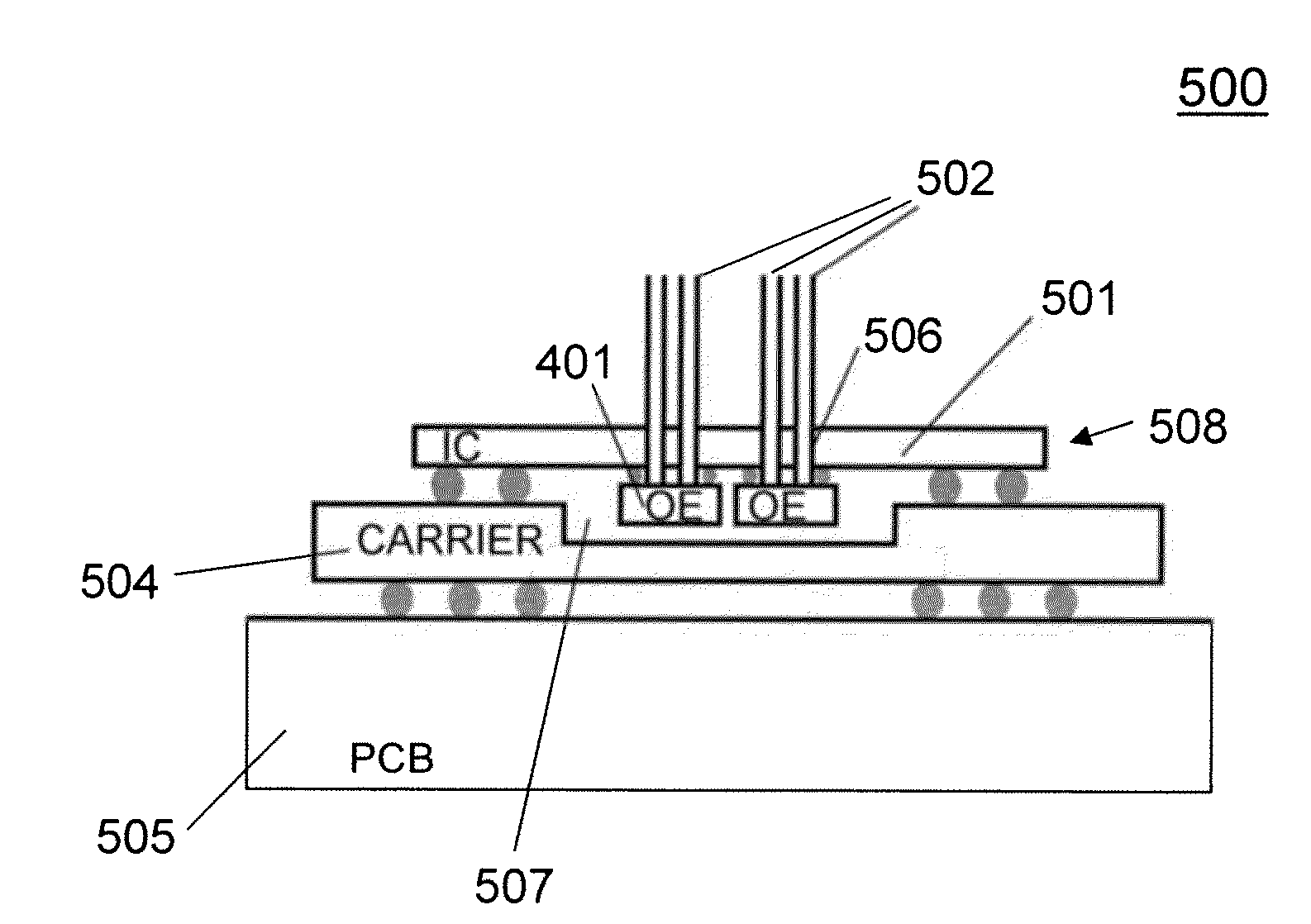
[0037]The invention disclosed herein describes a full optical and electrical packaging approach for interfacing multicore fibers with optoelectronic arrays, yielding complete multicore fiber optical links in a practical manner. Most generally, the concept includes butt-coupling between arrays of VCSELs or photo detectors (PDs) and arrays of cores contained in a single fiber cladding (i.e., a multicore fiber). In a previous publication by B. Rosinski, et al., a multicore fiber has been butt-coupled to a linear VCSEL array, but never has a VCSEL array been laid out to match the core geometry in a 2D fashion so that each core is matched to a VCSEL (or PD), in combination with using multicore fibers or an array of multicore fibers.

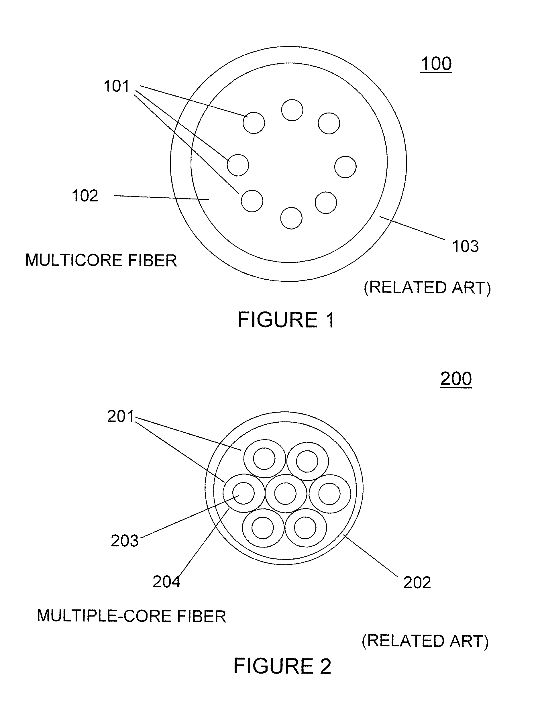
[0038]FIG. 1 exemplarily shows multicore optical ...


PUM


Abstract

A method and structure for coupling to a plurality of multicore optical fiber strands. A first plurality of optoelectronic devices is provided on a surface of a substrate, the first optoelectronic devices being arranged in a 2D array pattern that corresponds to a 2D array pattern corresponding to different light cores of a first multicore optical fiber. A second plurality of optoelectronic devices is provided on the surface of the substrate, the second optoelectronic devices being arranged in a 2D array pattern that corresponds to a 2D array pattern corresponding to different light cores of a second multicore optical fiber. Each optoelectronic device on the substrate surface provides one of a receive function and a transmit function for interacting with a corresponding core of a multicore optical fiber strand.

Description

Cross-Reference To Related Applications[0001]The present Application is related to U.S. Provisional Patent Application No. 61 / 364,856, filed on Jul. 16, 2010, by Doany, et al., entitled “PACKAGED MULTICORE FIBER OPTICAL TRANSCEIVER MODULE”, which provisional application is assigned to the present assignee and incorporated herein by reference.STATEMENT REGARDING FEDERALLY SPONSORED RESEARCH OR DEVELOPMENT[0002]This invention was made with government support under Contract No. H98230-07-C-0409, awarded by the Department of Defense (DOD). The government has certain rights in the invention.BACKGROUND OF THE INVENTION[0003]1. Field of the Invention[0004]The present invention generally relates to packaging fiber optical modules. More specifically, a multicore fiber is butt-coupled to a 2D array having a corresponding pattern that matches and aligns with that of the cores in the fiber, using flip-chip mounting involving a hybrid combination of two chip types, including a first chip type ha...

Claims


Application Information

Patent Timeline
Patent Type & Authority Applications(United States)
IPC IPC(8): G02B6/122G02B6/02G02B6/13
CPCG02B6/02042G02B6/43G02B6/4202
Inventor DOANY, FUAD ELIASKUCHTA, DANIEL MICHAELLEE, BENJAMIN GILESPEPELJUGOSKI, PETARSCHOW, CLINT LEE
Owner IBM CORP
Why Eureka
Try Eureka