Autogyro with pre-rotation

a technology of autogyro and pre-rotation, which is applied in the direction of rotorcraft, vehicles, aircrafts, etc., can solve the problems of inability to take off vertically and hover, inconvenient mechanical pre-spin devices on the market, and inconvenient use of them, so as to optimize the autogyro performance, optimize the takeoff run, and optimize the effect of performan

Inactive Publication Date: 2012-02-02
HSUEH THOMAS
View PDF10 Cites 16 Cited by
  • Summary
  • Abstract
  • Description
  • Claims
  • Application Information

AI Technical Summary

Benefits of technology

[0013]The disclosed apparatus in a first embodiment utilizes a variable pitch propeller and a lightweight, low rpm high torque electric motor (or motors) in line with and directly coupled to the rotor shaft (or shafts). The motor may be powered by an on-board battery which may be charged by a generator coupled to the main propulsion engine or the battery may alternatively be charged directly by the generator. An electronic control system may be used to manage the power distribution from the electric motor, to the main propulsion engine and to a propeller pitch control mechanism, so as to achieve optimum performance. At takeoff, the engine may be started with the propeller at zero pitch and the rotor-driving electric motor is engaged to spin the lift rotor to the desired take off speed while the autogyro is still stationary on the ground. To achieve flight, the pitch of the pusher propeller may be switched from zero pitch to the take off power pitch so as to obtain desired forward thrust while the power to the lift rotor is switched off as the autogyro begins to lift off the ground. In this way the rotor speed decay is little or none and the takeoff run may be relatively short. Also, if sufficient head wind is present, vertical takeoff would be possible.Second Embodiment
[0014]The disclosed apparatus in a second embodiment incorporates a collective rotor pitch control system to the first embodiment. The takeoff procedure is the same as in the first embodiment, except that the pitch of the rotor blades may be changed from zero to normal flight mode as soon as the pusher propeller provides maximum forward thrust. Again, the exact power flow sequence to the electric motor, engine, rotor and propeller pitch control could be managed by an electronic control system so as to optimize the autogyro performance. With this second version a vertical takeoff and landing can be achieved.
[0015]Both disclosed embodiments allow safer landing in case of engine failure than is achievable with a conventional autogyro because power is available to drive the rotor through the electric motor just prior to touchdown allowing for a lower touchdown forward speed. In the second version, the rotor pitch can also be changed to provide lift and maintain lift rotor speed, allowing the pilot to use the collective pitch to control the decent rate and make a softer landing. An electronic control system could also be programmed to optimize the landing procedure.

Problems solved by technology

The two major limitations of a conventional autogyro compared to a helicopter are its inability to takeoff vertically and to hover.
The available mechanical pre-spin devices on the market are not very satisfactory, chiefly because they are mechanically complex, switching power to and from the lift rotor takes time, and the lift rotor speed decays quickly.
The devices are often fragile, underpowered and unreliable.

Method used


Image

  • Autogyro with pre-rotation
  • Autogyro with pre-rotation
  • Autogyro with pre-rotation

Examples


first embodiment

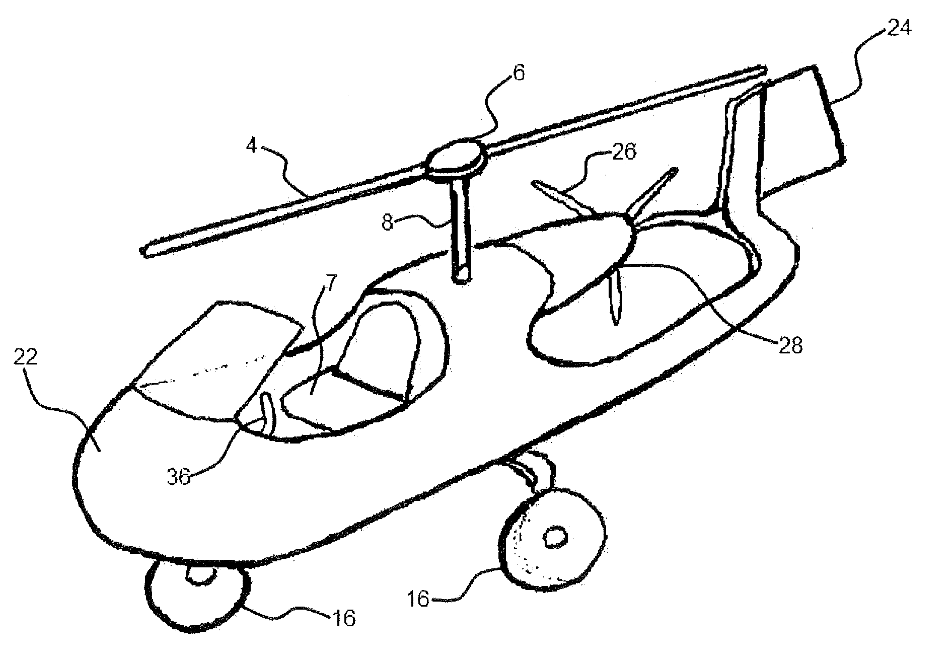
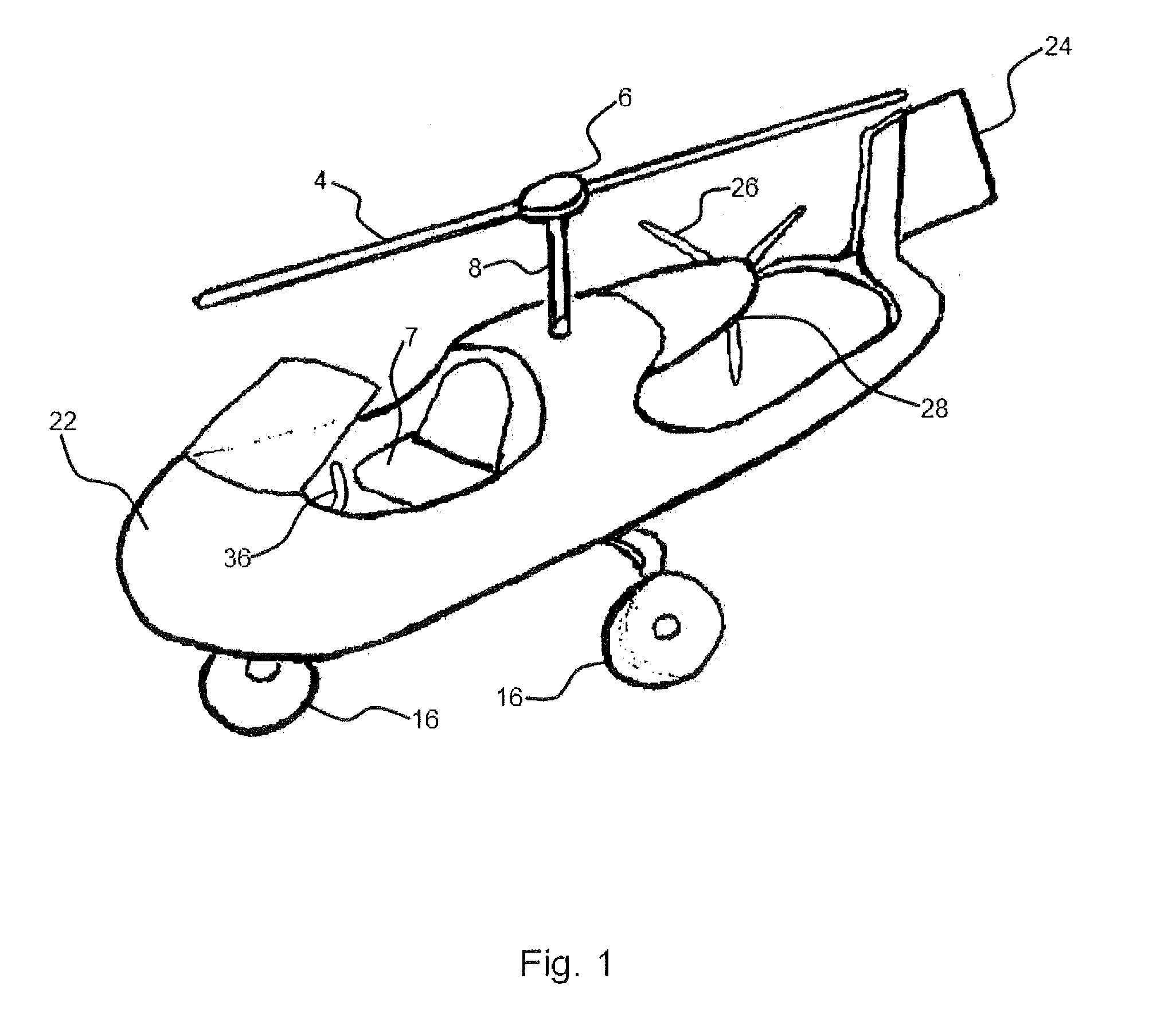
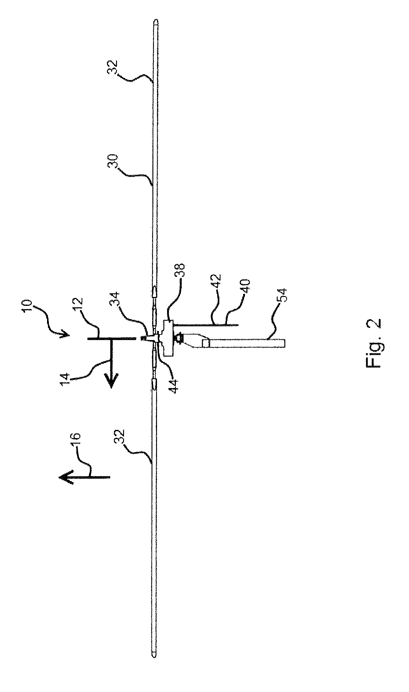
[0026]The first disclosed embodiment in one form uses a lightweight, low rpm high torque electric motor or motors in line with, and directly or indirectly coupled to the rotating shaft of one or more lift rotors. The lift rotor electric motor is separate from the main propulsion engine, in one form, a standard DC motor is utilized for the lift rotor electric motor. The lift rotor electric motor is powered by on-board battery or by an engine driven generator.

[0027]In function, a user would position the autogyro for takeoff, set the propeller pitch to zero, start the engine and then activate the electric motor to establish pre-rotation of the rotor. Once the rotor has reached the desired rpm, the pilot would activate the interlink which would automatically increase the pitch of the propeller and disconnect power to the rotor as soon as sufficient forward speed to sustain autorotation is achieved. The pilot would most likely be applying full engine power to the thrust propeller. The ex...

second embodiment

[0029]The author's second embodiment, in one form, adds a collective rotor pitch control system to the first version embodiment and may be used in conjunction with the first embodiment.

[0030]As in the first embodiment, the pilot would set the propeller pitch to zero, start the propulsion engine and then activate a switch to energize the electric motor to establish pre-rotation of the rotor. The pitch of the rotor blades would initially be at zero setting, thus producing no lift, and the rotor would be accelerated to a higher than normal flight rpm. When the rotor has reached the desired rpm, the propeller pitch would be increased while applying full engine power and simultaneously switching the rotor blades to normal flight mode pitch just prior to disconnecting power to the rotor motor. The resulting sudden surge of rotor lift produced by the stored kinetic energy at the higher rpm will cause the autogyro to “jump” into the air and continue climbing upon application of full engine ...


PUM


Abstract

The disclosed apparatus is an autogyro which utilizes a variable pitch propeller and an electric motor coupled to the lift rotor. At takeoff, the engine may be started with the thrust propeller at zero pitch and the lift rotor-driving electric motor is engaged to spin the lift rotor to the desired take off speed while the autogyro is still stationary on the ground. The pitch of the pusher propeller is switched from zero pitch to the take off power pitch so as to obtain desired forward thrust while the power to the lift rotor is switched off as the autogyro begins to lift off the ground. In this way the takeoff run may be relatively short. Also, if sufficient head wind is present, vertical takeoff would be possible.

Description

RELATED APPLICATIONS[0001]This application claims priority benefit of U.S. Provisional Application Ser. No. 61 / 367,995, filed Jul. 27, 2010 and incorporated herein by reference.BACKGROUND OF THE DISCLOSUREField of the Disclosure[0002]The improvements disclosed herein are applicable to autogyro-type aircraft (generally referred to as autogiros, autogyros, gyroplanes and gyrocopters), such as the typical autogyro shown in FIG. 1 and the autogyro of U.S. Pat. No. 4,653,705 filed on Feb. 19, 1981 and incorporated herein by reference. Autogyros are distinguished from airplanes, which have a fixed wing and one or more propellers or other engines, and helicopters, which have one or more powered rotors.[0003]An autogyro has a rotor that can turn freely on a vertical axis. Forward propulsion is provided by a conventional pusher or puller propeller. In forward flight the rotor disk is inclined backwards at a positive angle of attack resulting in aerodynamic forces which spin the rotor and pro...

Claims


Application Information

Patent Timeline
Patent Type & Authority Applications(United States)
IPC IPC(8): B64C27/02
CPCB64C27/025
Inventor HSUEH, THOMAS
Owner HSUEH THOMAS
Why Eureka
Try Eureka