Electrical architecture for a rotary wing aircraft with a hybrid power plant

a hybrid power plant and electric architecture technology, applied in the field of rotary wing aircraft, can solve the problems of reducing the options of making architectures and their components, conflicting with having any guarantee of electrical architecture capability, and reducing the number of electrical architectures, so as to achieve the effect of effective lightening the load on the engine, saving overall energy consumption, and considerable ecological impact of invention

Active Publication Date: 2012-02-02
EUROCOPTER
View PDF12 Cites 138 Cited by
  • Summary
  • Abstract
  • Description
  • Claims
  • Application Information

AI Technical Summary

Benefits of technology

[0086]In particular, the invention makes it possible to share selected resources, and to make functions available on various types of rotary wing aircraft (e.g. lightweight aircraft) that until now have not been accessible, and also to make it possible more effectively to lighten the load on the engine (e.g. the gas generator, and consequently the starter / generator), thereby achieving overall energy consumption savings. The ecological impact of the invention is considerable.

Problems solved by technology

One of these problems stems from the practical difficulty of being able to propose an electrical architecture that is light in weight, reliable, and suitable for hybrid drive, on numerous aircraft models.
This is that much more difficult when for a given aircraft it is desired that hybrid drive should be available as an option.
Such a variety of configurations thus reduces options for making architectures and their components more uniform between models of a given range of aircraft and between different ranges from the same manufacturer.
However, technological, economic, and environment constraints (weight, safety, regulations, .
. . ) may conflict with having any guarantee of the electrical architecture being capable of providing the necessary energy distribution and recharging.
All of those problems are made more critical when the aircraft needs to incorporate additional functions that consume large amounts of energy, such as de-icing, winching, ventilation, and air conditioning.
According to known documents, electrical architectures for power plants (single main engine and auxiliary motor) are interdependent and therefore provide no solution that is acceptable in practice in this field.
Another problem is associated with the fact that demand is increasing for additional and sophisticated items of on-board equipment (de-icing, winching, fans, air conditioning, etc.).
The on-board weight of an aircraft is thus tending to increase, and this can even happen during its lifetime.
From this point of view, in spite of equipment being optimized, the draconian steps taken to reduce weight can, in practice, constitute an obstacle to providing hybrid drive.
A fortiori, adding hybrid drive as an option or as standard (including functional structures that may represent a weight of the order of several tens of kilograms, i.e. more than the weight of all of the other electricity generator structures), is contradictory and may even be impossible if a model of aircraft is already close to its authorized weight limit.
In conclusion, it can be understood that it is not easy to design, adapt, and produce a hybrid power plant and its architecture so as to have an impact that is favorable in terms of performance (in particular for a multi-engined aircraft such as a twin-engined aircraft), or in terms of safety (in particular for an aircraft having a single engine).

Method used


Image

  • Electrical architecture for a rotary wing aircraft with a hybrid power plant
  • Electrical architecture for a rotary wing aircraft with a hybrid power plant
  • Electrical architecture for a rotary wing aircraft with a hybrid power plant

Examples


Embodiment Construction

[0094]Embodiments of the invention are described below with reference to the figures.

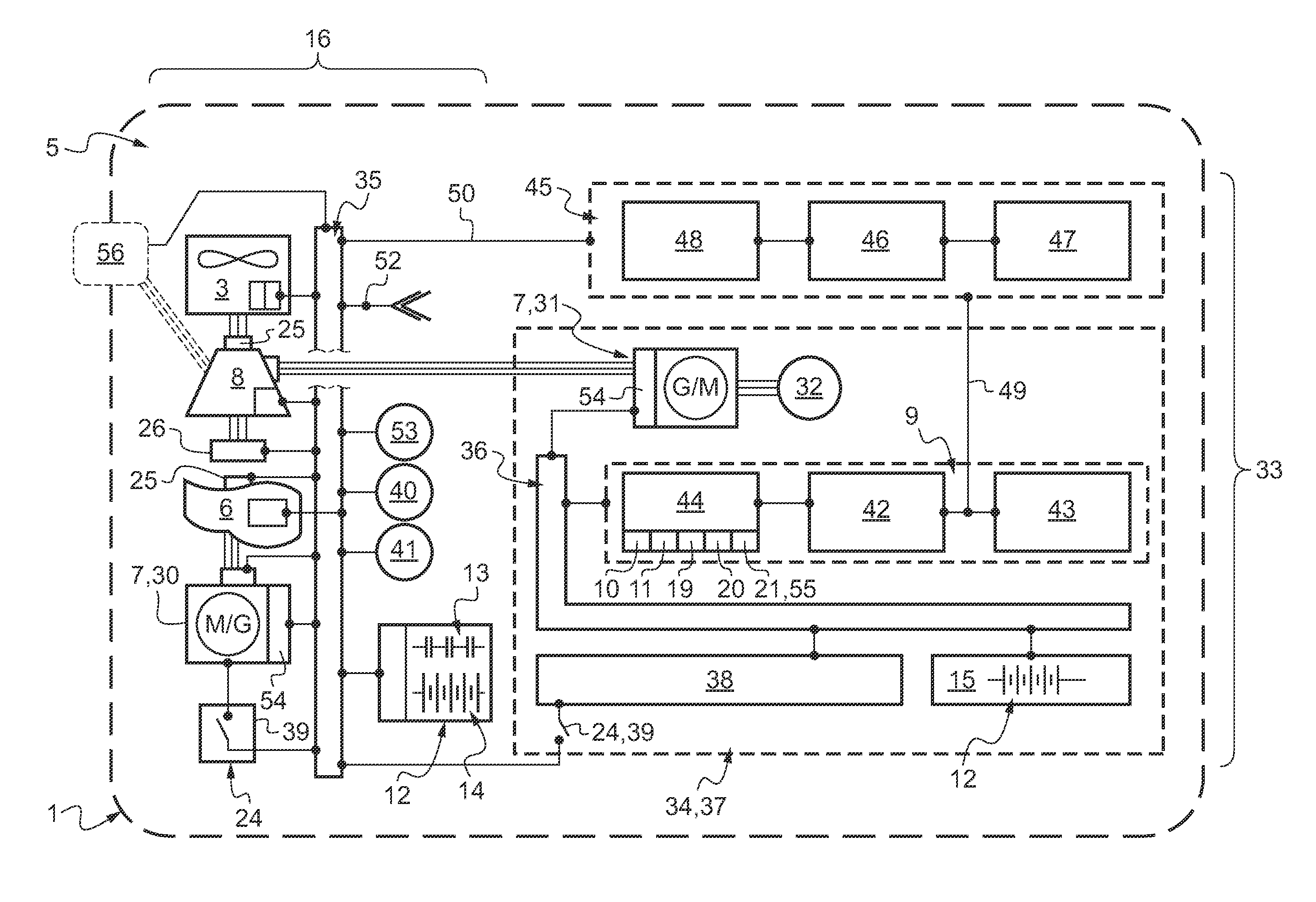
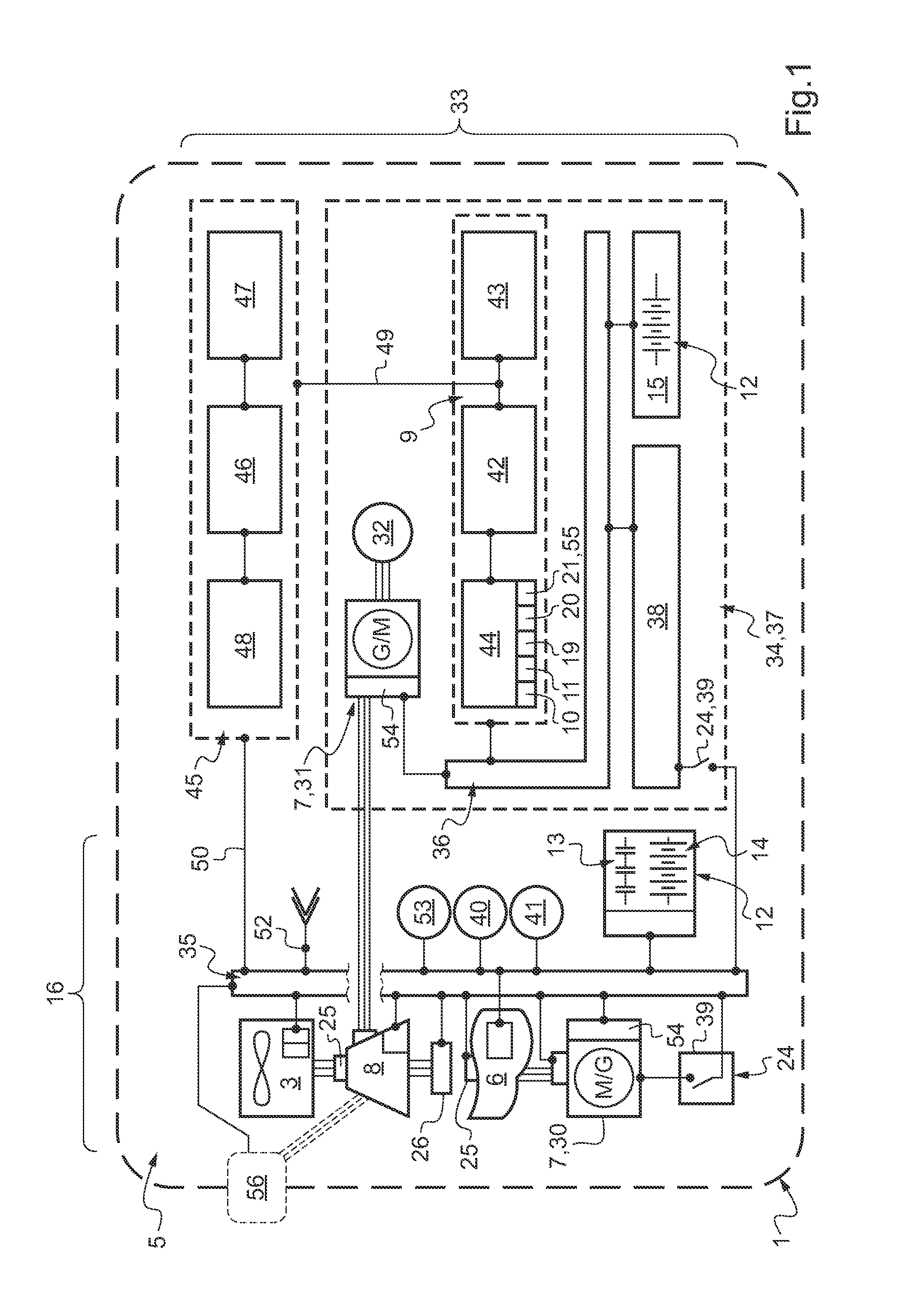
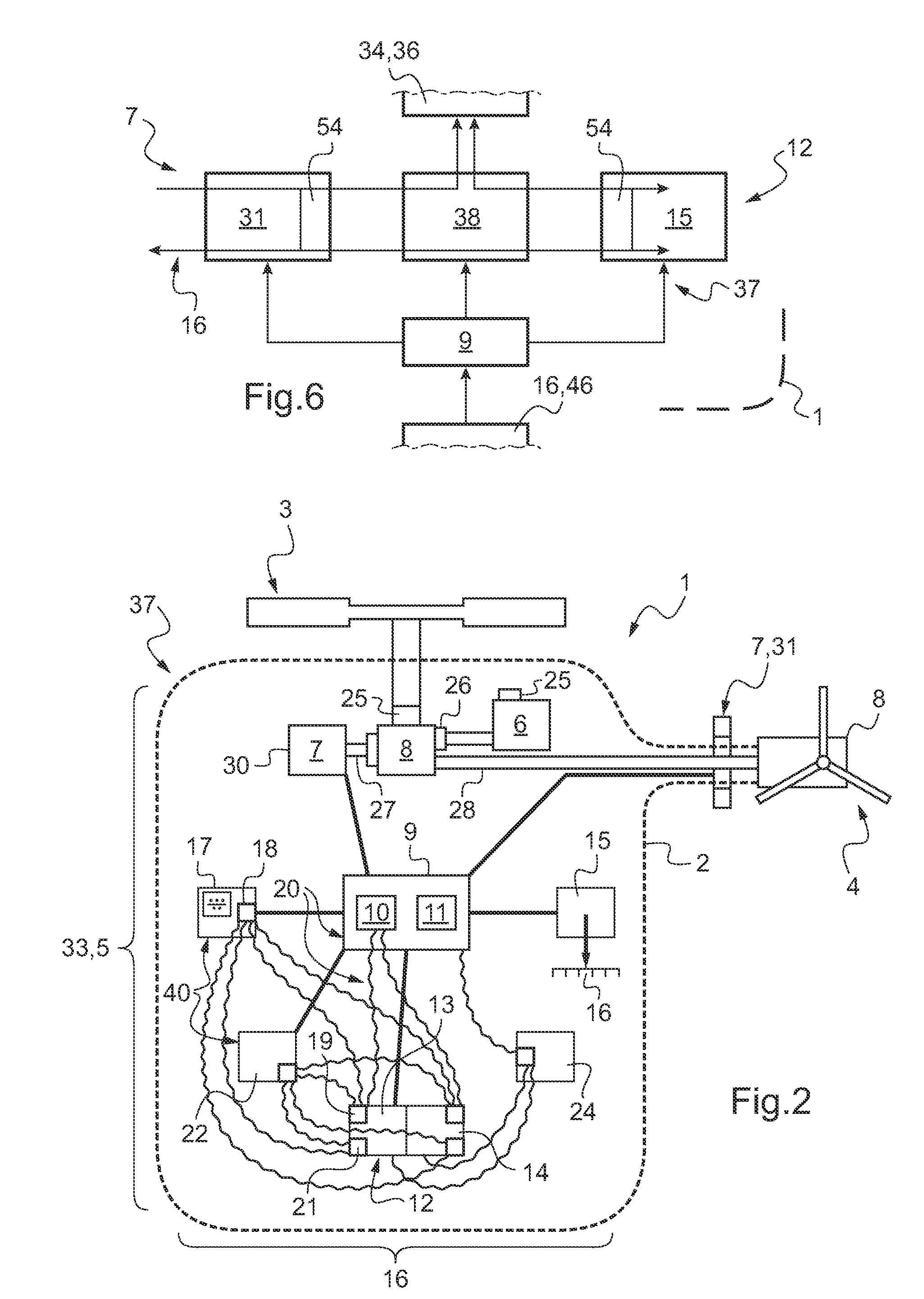
[0095]FIG. 2 shows a rotary wing aircraft 1, here in the form of a helicopter, having an airframe 2, a main lift rotor 3, and an anti-torque tail rotor 4. A power plant 5 comprises a (main) engine 6 and two electrical machines 7 contributing to providing drive. These two machines 7 are coupled mechanically to at least one transmission 8. In this example, each of these two machines 7 is mechanically coupled to a respective distinct gearbox, one to the main gearbox (MGB) and the other to the tail gearbox (TGB).

[0096]Naturally, most of the components of the power plant 5 also include power electronics. This applies in particular when the machine(s) 7 is / are usable as electric motors.

[0097]In this example, one of the electrical machines 7 (referenced 30 and referred to as an electric starter with a generator function) is coupled directly only to the main gearbox 8 or MGB, which is also coupled mechanica...


PUM


Abstract

A hybrid power plant (5) for an aircraft (1) comprises at least: a hybrid drive system (37) having a main on-board electricity network (16) and an auxiliary electricity network (34); and a selective adaptation interface (38) arranged to enable electrical energy to be exchanged selectively between the main and auxiliary electricity networks (16; 34). At least one engine and a hybrid drive auxiliary electrical machine (7, 31) are mechanically connected to a transmission (8); said machine (7) being electrically connected to at least one auxiliary electrical bus (36) in parallel with at least one auxiliary device for delivering electric charge.

Description

CROSS REFERENCE TO RELATED APPLICATIONS[0001]This application claims the benefit of FR 10 02867 filed on Jul. 8, 2010, the disclosure of which is incorporated in its entirety by reference herein.BACKGROUND OF THE INVENTION[0002](1) Field of the Invention[0003]The invention relates to the field of rotary wing aircraft (e.g. helicopters, rotorcraft, etc.). It relates more particularly to so-called “hybrid” modes of driving the rotation of at least one rotor via a gearbox of the aircraft.[0004](2) Description of Related Art[0005]As in the automobile field, a power plant is said herein to be “hybrid” when it is possible to obtain mechanical power by selecting between a combustion source, an electrical source, or both sources together.[0006]Although in practice no hybrid helicopters are presently being mass-produced, numerous types of rotary wing aircraft may be concerned by the invention.[0007]A rotary wing aircraft of the invention may include one or more lift rotors referred to as “ma...

Claims


Application Information

Patent Timeline
Patent Type & Authority Applications(United States)
IPC IPC(8): B64C27/04B64C27/12B60L50/15B60L50/16
CPCB60L3/0046Y02T50/64B60L11/005B60L11/123B60L11/14B60L11/1853B60L2210/20B60L2240/36B60L2250/10B64C27/04B64C27/14B64D27/24B64D2027/026Y02T10/6217Y02T10/7005Y02T10/7022Y02T10/705Y02T10/7077Y02T10/725Y02T50/44B60L3/0061B60L50/40B60L50/61B60L50/16B60L58/18Y02T10/62Y02T10/70Y02T10/72Y02T10/7072Y02T50/40Y02T50/60B64C27/08B64C27/12B64D31/00B64D47/00
Inventor HOPDJANIAN, MARIE-LAURECONNAULTE, MATTHIEUGAZZINO, MARCMERCIER, CHRISTIAN
Owner EUROCOPTER
Why Eureka
Try Eureka