Combustor and the Method of Fuel Supply and Converting Fuel Nozzle for Advanced Humid Air Turbine

a technology of advanced humid air turbines and combustor, which is applied in the ignition of turbine/propulsion engines, engine starters, lighting and heating apparatus, etc., can solve the problems of reducing the heating value recovered, and affecting the combustion efficiency of the combustion air

Active Publication Date: 2012-02-09
MITSUBISHI POWER LTD
View PDF19 Cites 16 Cited by
  • Summary
  • Abstract
  • Description
  • Claims
  • Application Information

AI Technical Summary

Benefits of technology

[0026]According to the invention, it is possible to realize a fuel control method and a fuel control device of a gas turbine combustor for advanced humid air turbines, in which method and device the gas turbine combustor can perform combustion ...

Problems solved by technology

Generally, due to changes in compressor intake air flow rate and a vibration characteristic of a rotating body upon an increase in number of revolutions at the start of a gas turbine, there is a tendency that a system is liable to become unstable due to disturbance as compared with the case after a rated revolution speed is reached.
Further, since decrease in flame temperature upon burning in a gas turbine combustor leads to decrease in heating value recovered in a regenerator, decrease in combustion air temperature leads to decrease in flame temperature and reduction in generation of NOx.
That is, it has been found that even when a humidification tower feed water volume is held under a particular condition in a state of humidification, increase in mois...

Method used


Image

  • Combustor and the Method of Fuel Supply and Converting Fuel Nozzle for Advanced Humid Air Turbine
  • Combustor and the Method of Fuel Supply and Converting Fuel Nozzle for Advanced Humid Air Turbine
  • Combustor and the Method of Fuel Supply and Converting Fuel Nozzle for Advanced Humid Air Turbine

Examples


first embodiment

[0053]Fuel control method and a fuel control device of a gas turbine combustor, according to the invention, mounted on an advanced humid air turbine will be described hereinafter with reference to FIGS. 1 to 6.

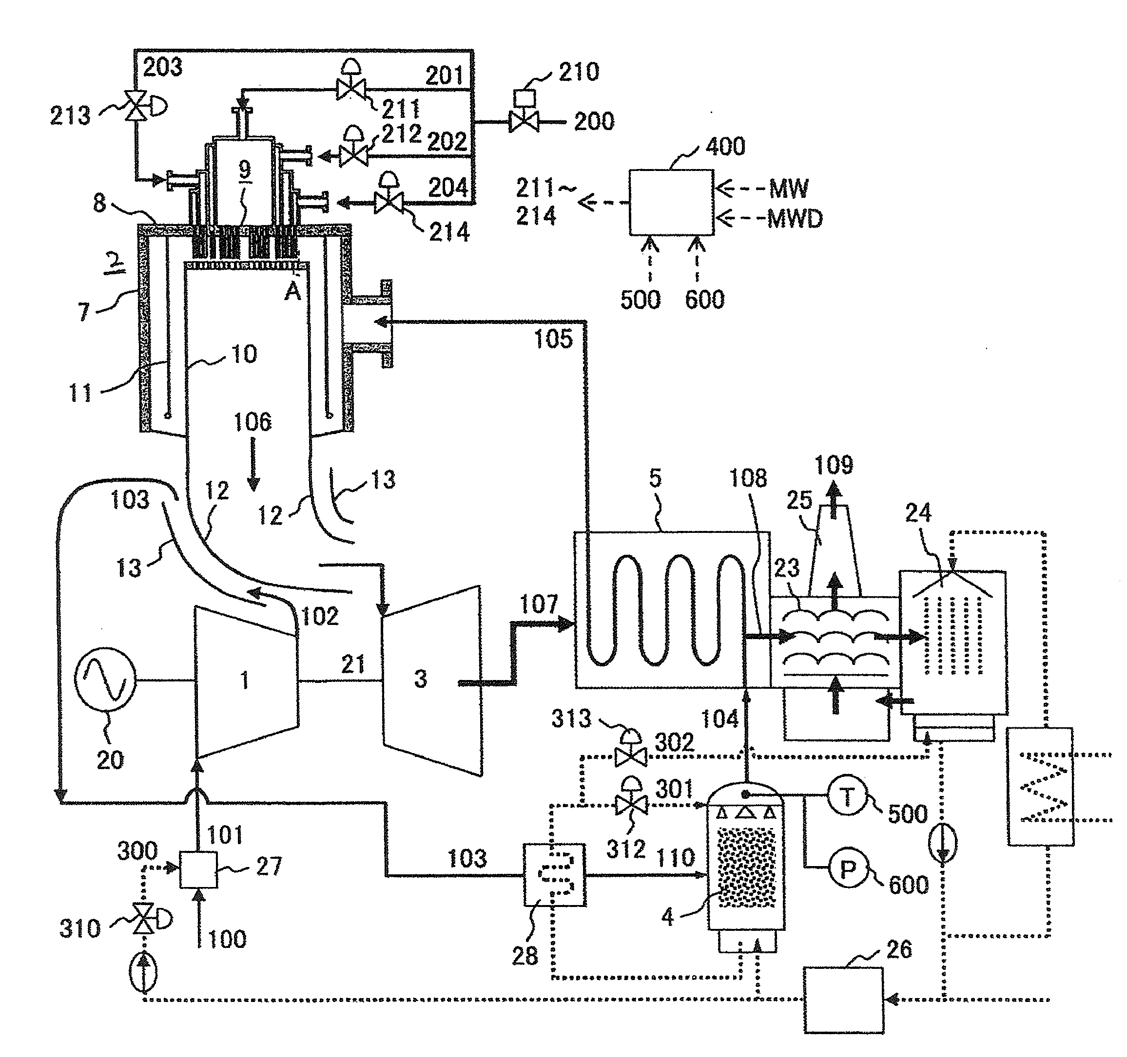
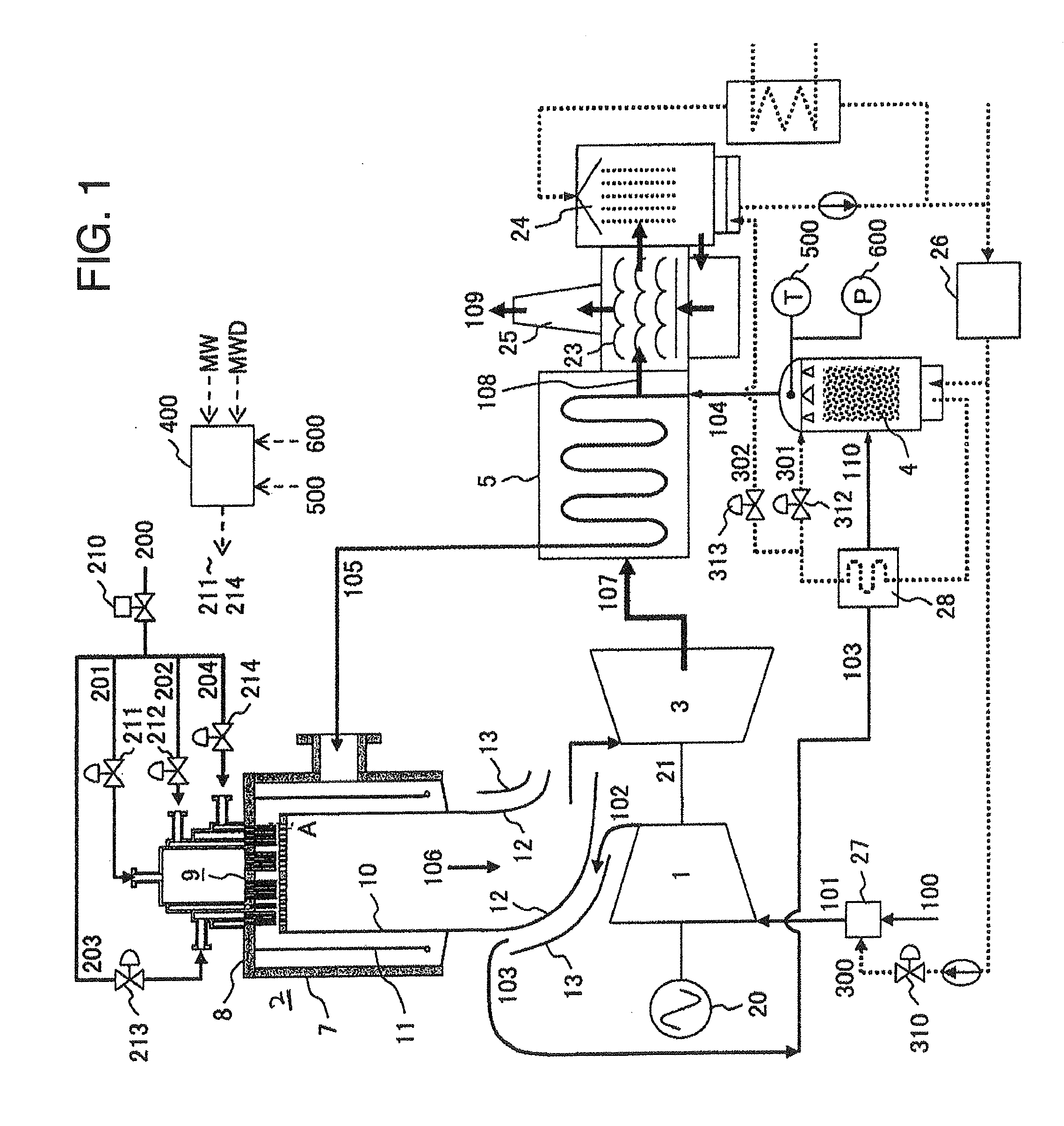
[0054]FIG. 1 is a system diagram showing whole construction of an advanced high humid air turbine, on which a gas turbine combustor according to a first embodiment of the invention is mounted.

[0055]An advanced high humid air turbine for power generation comprises a compressor 1 for compressing air, a gas turbine combustor 2, which uses compressed air compressed by the compressor 1 to burn fuel to generate combustion gas, a turbine 3 driven by the combustion gas generated in the gas turbine combustor 2, a humidification tower 4 for humidification of the compressed air compressed by the compressor 1 and fed to the gas turbine combustor 2, and a recuperator 5, in which water fed to the humidification tower 4 is heated by exhaust gases discharged from the turbine 3, and output of ...

second embodiment

[0116]Referring to FIGS. 7 to 9, an explanation will be given to fuel control method and a fuel control device of a gas turbine combustor, mounted in an advanced humid air turbine.

[0117]Since the fuel control device of the gas turbine combustor according to the embodiment is common in fundamental construction to the fuel control device of the gas turbine combustor according to the first embodiment, an explanation common to the both is omitted and only different portions will be described hereinafter.

[0118]A F1 bias calculator 404 in a fuel control device 400 of the gas turbine combustor 2 according to the second embodiment is different from that of the fuel control device of the gas turbine combustor 2 according to the first embodiment in that in place of a measured value of humidification tower internal temperature 500, saturated humidity of humid air 104 is found using one of measured values of humidification tower feed water temperature 501, humidification tower circulating wate...

third embodiment

[0128]Referring to FIGS. 10 to 13, an explanation will be given to fuel control method and a fuel control device of a gas turbine combustor according to the invention, mounted in an advanced humid air turbine.

[0129]Since the fuel control method and the fuel control device of the gas turbine combustor according to the third embodiment are common in fundamental construction to the fuel control method and the fuel control device of the gas turbine combustor according to the first embodiment, an explanation common to the both is omitted and only different portions will be described hereinafter.

[0130]A fuel control device 400 of the gas turbine combustor 2 according to the third embodiment is different from the fuel control device of the gas turbine combustor 2 according to the first embodiment in that an economizer 22 is mounted downstream of the recuperator 5 for heat recovery from the gas turbine exhaust gas 107. The economizer 22 has an advantage in that the advanced humid air turbin...


PUM


Abstract

A fuel control device and method of a gas turbine combustor, for advanced humid air turbines, in which plural combustion units comprising plural fuel nozzles for supplying fuel and plural air nozzles for supplying air for combustion are provided. A part of the plural combustion units are more excellent in flame stabilizing performance than the other combustion units. A fuel ratio, at which fuel is fed to the part of the combustion units is set on the basis of internal temperature of the humidification tower and internal pressure of the humidification tower to control a flow ratio of the fuel fed to the plural combustion units.

Description

BACKGROUND OF THE INVENTION[0001]The present invention relates to a fuel control method and a fuel control device of a gas turbine combustor for advanced humid air turbines for stably operating a low NOx gas turbine combustor mounted on an advanced humid air turbine.[0002]Publicly known JP-A-2008-175098 discloses a technology relating to fuel control capable of maintaining flame stability while ensuring a low NOx performance of a combustor before and after starting of moisture addition in an advanced humid air turbine power-generating plant, in which an improvement is achieved in output and efficiency by adding a moisture to a gas turbine working fluid (air) to humidify the same and using the humidified air to recover thermal energy possessed by gas turbine exhaust gases.[0003]Generally, due to changes in compressor intake air flow rate and a vibration characteristic of a rotating body upon an increase in number of revolutions at the start of a gas turbine, there is a tendency that ...

Claims


Application Information

Patent Timeline
IPC IPC(8): F02C7/22
CPCF02C6/18F02C9/28F23L7/005F02C7/22F23R3/28F23R3/346F23R3/12
Inventor ABE, KAZUKIKOGANEZAWA, TOMOMI
Owner MITSUBISHI POWER LTD
Why Eureka
Try Eureka