Liquid separation device

a separation device and liquid technology, applied in the direction of separation process, multi-stage water/sewage treatment, lighting and heating apparatus, etc., can solve the problems of affecting the extraction of liquid, not desirable, and very present remoistening, so as to improve the thickness of the matter, and improve the drying rate or level

Active Publication Date: 2012-02-09
GEA FARM TECH CANADA
View PDF12 Cites 11 Cited by
  • Summary
  • Abstract
  • Description
  • Claims
  • Application Information

AI Technical Summary

Benefits of technology

[0029]Among other objectives, the present invention seeks to improve the drying rate or level in order to separate the liquid portion of matter from the solid portion and to reuse the latter for providing biological litter, for example, to be used for animals, and further to provide a better control of the drying rate for the produc

Problems solved by technology

It is also known that a substantial problem associated with conventional liquid separating systems is that remoistening is very present when carrying out liquid separation (“dewatering”) by compression under rollers.
When the matter exits from between two rollers, these droplets captured in the porosities of the roller return into the material to be processed, which is not desirable.
Another substantial problem associated with conventional liquid separating systems is that the extracting of liquid is also influenced by the pressure applied to the matter to be processed.
Since the matter enters in a random fashion, it often occurs that certain areas of the bed have less matter, and therefore practically no compression pressure is available while it is distributed on the environing matter.
The current conventional technologies of “screw press” type succeed in obtaining drying rates in this order, however their mechanical configuration damages the fibre which constitutes the solid matter.
The behaviour of the bacteria in the litter and the comfort of the animals is thus compromised.
For each additional perce

Method used


Image

  • Liquid separation device
  • Liquid separation device
  • Liquid separation device

Examples


Embodiment Construction

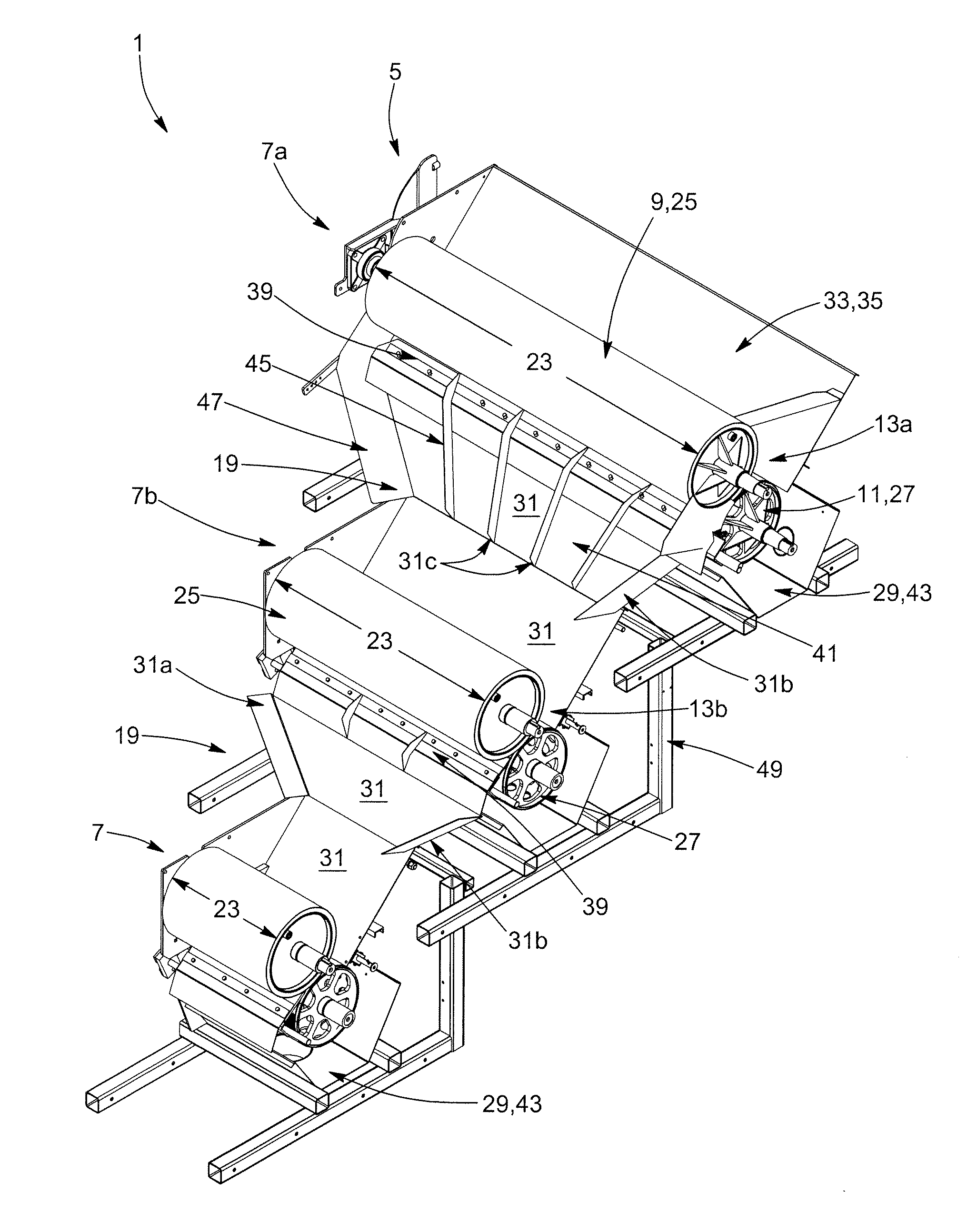
[0052]In the following description, the same numerical references refer to similar elements. The embodiments, geometrical configurations, materials mentioned and / or dimensions shown in the figures or described in the present description are preferred embodiments only, given for exemplification purposes only.

[0053]Moreover, although the present invention was primarily designed for use in the field of agriculture, farming and / or the like, for processing a mixture material typically containing at least some liquid material and at least some solid material, among other possible substances, such a manure and / or various other possible materials, the invention may be used with various other types of objects, and in various other fields, for applications where liquid material, or at the very least a substantially “liquid” material, would have to be separated from a compressible solid material, or at the very least from a substantially “non-liquid” material, as can be easily understood by a ...


PUM

PropertyMeasurementUnit
Speedaaaaaaaaaa
Widthaaaaaaaaaa
Heightaaaaaaaaaa

Abstract

A liquid separating device (1) for processing a mixture material (3) containing both solid and liquid materials (3a,3b), in order to separate liquid material (3b) from the solid material (3a), the liquid separating device (1) includes a support frame (5), a series of liquid separation assemblies (7a,7b) and a corresponding guiding assembly (19) between each pair of liquid separation assemblies (7). The liquid separation assemblies (7) are disposed about the support frame (5) in a cascading configuration, and the passage (13) of each liquid separation assembly (7) is narrower in width than the passage of a preceding liquid separation assembly (7) so that each subsequent liquid separation assembly (7b) is enabled to extract more liquid material via an increased wringing pressure resulting from a thickening of the remaining mixture material (3) to be processed and the narrower subsequent passage (13b) through which it is channeled and pressed.

Description

FIELD OF THE INVENTION[0001]The present invention relates to a liquid separating device. More particularly, the present invention concerns a liquid separating device for processing a mixture material containing both solid and liquid materials, in order to separate liquid material from the solid material, and also relates to a kit for assembling the same, as well as to corresponding methods of operation and / or of assembly associated thereto.BACKGROUND OF THE INVENTION[0002]Liquid separating devices (or simply “separators”), such as manure separators for example, and the cascading press roller configurations used therewith, are known in the art, as shown in FIGS. 1-4, for example.[0003]Also known to the Applicant are the following US patent and patent applications which describe various other types of conventional separating mechanisms and / or roller assemblies: U.S. Pat. Nos. 1,339,600; 3,531,404; 3,699,881; 3,873,450; 3,906,853; 3,971,310; 4,070,175; 4,775,472; 4,879,034; 4,940,500; ...

Claims


Application Information

Patent Timeline
IPC IPC(8): B01D33/052B01D37/00
CPCA01C3/00B01D33/044B30B9/20B30B9/26F26B5/14F26B17/28B01D33/41B01D33/646
Inventor COURTEMANCHE, ALAINDESROCHERS, YANNBRISSON, JEROMEST-ONGE, STEPHANE
Owner GEA FARM TECH CANADA
Why Eureka
Try Eureka