
Holey single-mode optical fiber and optical transmission system using same

a single-mode optical fiber and optical transmission system technology, applied in the direction of optical waveguide light guide, optical light guide, instrument, etc., can solve the problems of difficult manufacturing and expensive, large loss of transmission, and absence of waveguide structure locally, so as to facilitate the manufacture of optical fiber and low cost

Inactive Publication Date: 2012-02-09
THE FUJIKURA CABLE WORKS LTD +1
View PDF5 Cites 17 Cited by
  • Summary
  • Abstract
  • Description
  • Claims
  • Application Information

AI Technical Summary

Benefits of technology

[0042]According to the present invention, by optimizing a parameter of an optical fiber (HAF) structure where a core with a large refraction index is provided at a center portion and holes are provided at the periphery of the core, it is possible to realize an optical fiber that has a cable cut-off wavelength of 1.0 μm or less, has a bending loss of 10 dB / m or less at a bending radius r of 10 mm over a wavelength of 1.0 to 1.625 μm, maintains a zero-dispersion wavelength between 1260 and 1460 nm, and has a small splice loss. Therefore, a WDM transmission at a wavelength of 1.0 to 1.625 μm may be possible. In addition, since the number of holes is small, it is possible to easily manufacture an optical fiber at a low cost.

Problems solved by technology

In addition, in these specifications, it is pointed out that, with one layer of holes, a light confinement in a long wavelength side is weak and thereby the transmission loss becomes large.
However, in the related art, there are problems as described below.
In the PCF 100 (see FIG. 21) used in Non-Patent Document 1, since the number of holes 102 is remarkably large, that is, 36 to 90, it is very difficult to manufacture and is expensive.
In addition, since a material of a center portion 103 and a material of a clad 101 are the same, in a case where holes are collapsed by a fusion splicing or the like, there is a problem in that a wave guide structure is locally absent and a loss at a splicing portion becomes large.
In the HAF used in Patent Document 1 and Non-Patent Document 2, since a zero-dispersion wavelength is near 1.0 μm, a chromatic dispersion becomes large at a wavelength of 1.55 μm or 1.625 μm, such that a waveform is distorted and thereby it becomes difficult to increase a transmission capacity.
Therefore, it becomes difficult to perform a WDM transmission across the entire wide wavelength band of a wavelength of 1.0 to 1.625 μm.
In addition, since holes are formed at positions adjacent to a core, it is difficult to remove a loss caused by irregularity of a hole portion or an absorption loss caused by a hydroxyl (OH) group and thereby it is difficult to reduce the loss.
In the PCF used in Patent Document 4, since the number of holes is large, it is difficult to manufacture and is expensive.
However, the MFD becomes remarkably small.

Method used


Image

  • Holey single-mode optical fiber and optical transmission system using same
  • Holey single-mode optical fiber and optical transmission system using same
  • Holey single-mode optical fiber and optical transmission system using same

Examples


examples

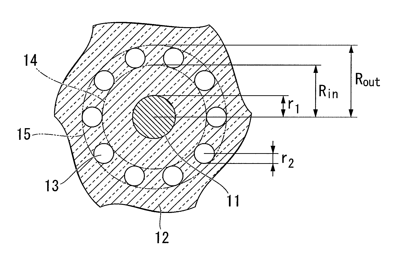
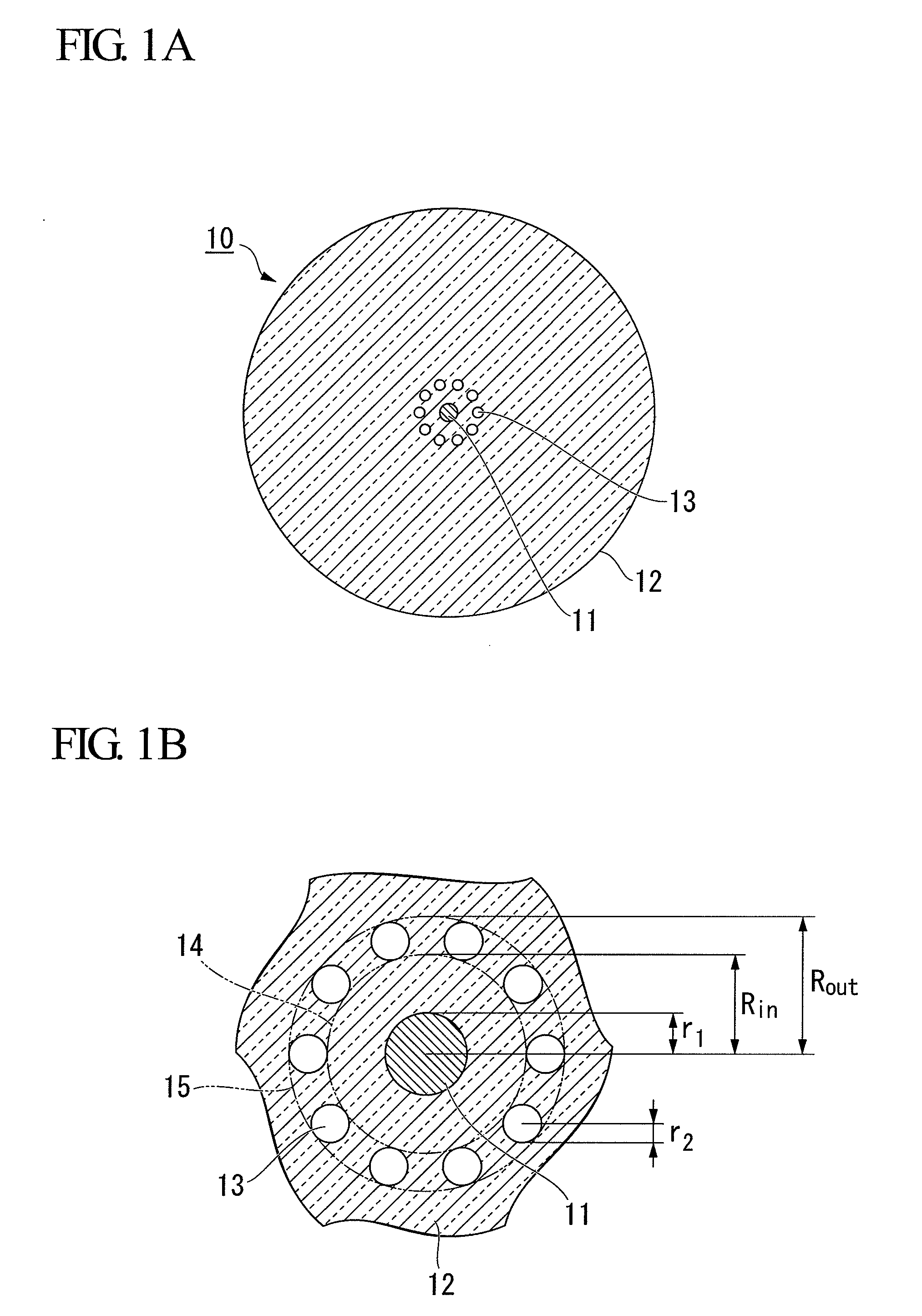
[0095]As described below, an HAF is actually manufactured with respect to a case where a refraction index of the clad 12 is set to a pure silica level, a refraction index of the holes 13 is set to 1 (air), the core 11 is made of a silica glass of which the refraction index is increased by using germanium (Ge) as a dopant material, and a step-type refraction index distribution is shown, and the relationship between structure parameters and optical characteristics is obtained.

[0096]A cable cut-off wavelength represents a value measured by a measurement standard of an optical fiber, that is, a 7.6.1 Cable cut-off method of IEC 60793-1-44. In addition, in a case where the number of holes is varied, a correlation of each of the optical characteristics increases when using an air-filling fraction F rather than when using a hole diameter, such that the air-filling fraction F shown in the above-described equation (1) is used.

[0097]Structure parameters and main optical characteristics of eac...

first example

A First Example

[0098]In a first example, a holey single-mode optical fiber having 10 holes 13 around a core 11 as shown in FIG. 1A was manufactured. In a cross section of the optical fiber, the holes 13 are disposed in a single concentric circle.

[0099]Parameters such as a core radius and a core Δ are shown in fibers A to E of Table 1. The fiber E is an optical fiber manufactured for comparison, in which a core diameter and a core Δ are the same and thereby holes are not present. In Table 1, both a zero-dispersion and a cable cut-off wavelength are shown.

[0100]As can be seen from the result, when the air-filling fraction F is 50% or less, it satisfies the cable cut-off wavelength of 1.0 μm or less. In addition, the air-filling fraction F of 50.1% in the fiber C becomes 50% in two significant digits and satisfies the above-described “air-filling fraction is 50% or less”. On the other hand, as shown in the result of the fiber E, when the air-filling fraction F is 54.1%, that is, when i...

second example

A Second Example

[0112]As a second example, an HAF was manufactured with a parameter shown in fibers F to I of Table 1. The fiber I is an optical fiber manufactured for comparison, in which a core diameter and a core Δ are the same and holes are not present.

[0113]From Table 1, it can be seen that a cable cut-off wavelength is 1.0 μm or less and a zero-dispersion wavelength is between 1260 and 1460 nm, and thereby the requirement was satisfied. Measurement results of an MFD and a bending loss of each of the fibers is shown in Tables 5 and 6.

TABLE 5MFD [μm] of each fiberMeasurement wavelength[μm]1.061.241.311.481.551.625Fiber F7.18.18.49.39.79.9Fiber G7.18.08.49.29.59.7Fiber H7.18.08.49.29.59.5Fiber I7.18.38.710.010.711.4

TABLE 6Bending loss [dB / m] at a bending radius r of 10 mm of each fiberMeasurement wavelength [μm]1.551.625Fiber F26.837.4Fiber G6.56.8Fiber H1.64.7Fiber I>100>100

[0114]As shown in Table 5, a mode field diameter of a wavelength of 1.31 μm was a large value such as 8.4 ...


PUM


Abstract

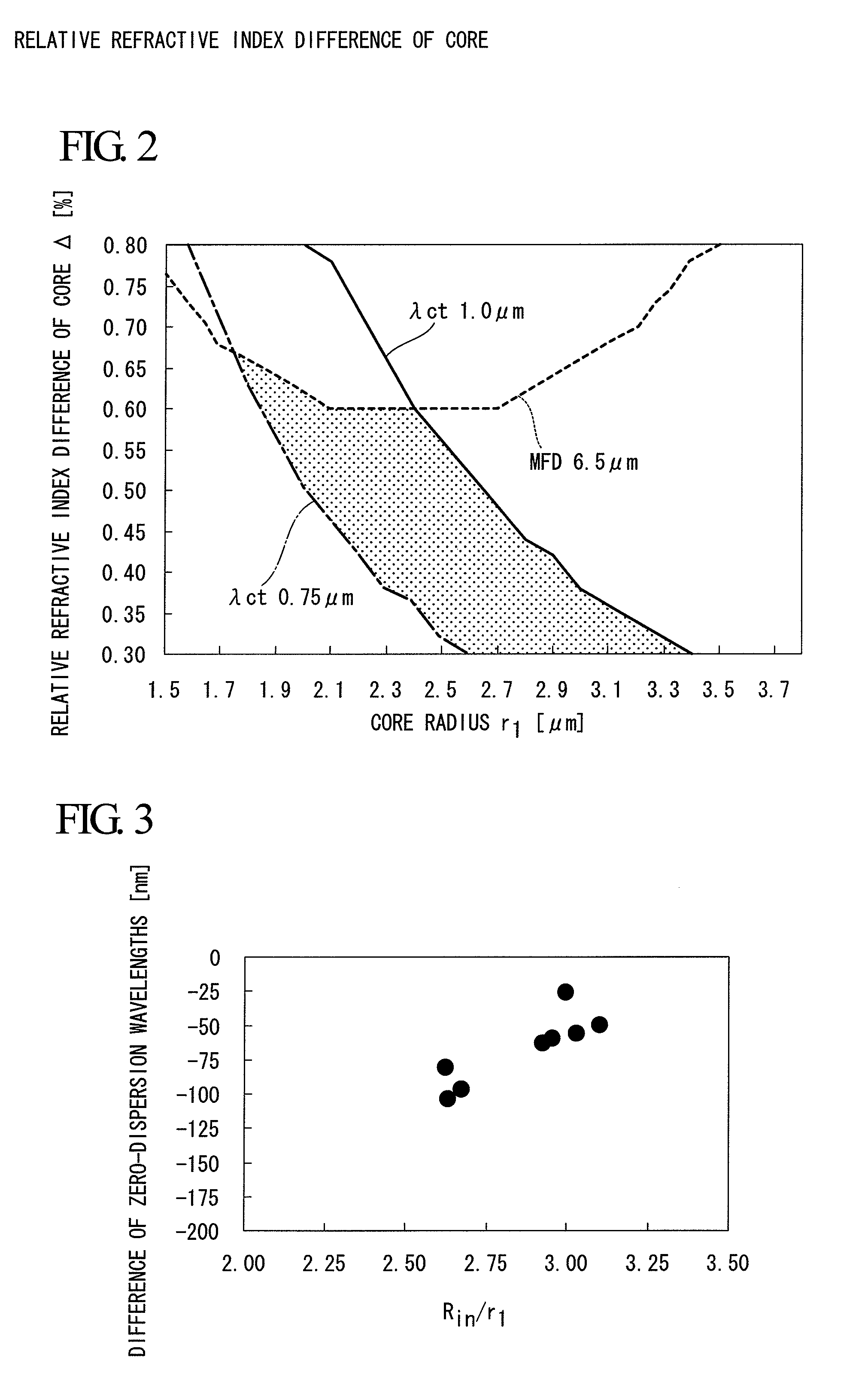
Provided is a holey single-mode optical fiber including a core not having holes, and a clad having holes extending in a longitudinal direction, in which a refraction index of the core is larger than that of a portion of the clad other than the holes, a radius r1 of the core is within a range of 2.2 to 3.2 μm, a relative refraction index difference Δ of the core to the clad is within a range of 0.3 to 0.56%, a distance Rin between a center of the core and an inner edge of the holes is 2.0 to 3.5 times the radius r1 of the core, an air-filling fraction F is within a range of 30 to 50%, a cable cut-off wavelength is 1.0 μm or less, a zero-dispersion wavelength is within a range of 1260 to 1460 nm, and a bending loss characteristic at a bending radius of 10 mm is 10 dB / m or less.

Description

CROSS-REFERENCE TO RELATED APPLICATION[0001]This is a Continuation Application of International Application No. PCT / JP2010 / 002887, filed on Apr. 21, 2010, which claims priority to Japanese Patent Application No. 2009-103224 filed on Apr. 21, 2009. The contents of the aforementioned applications are incorporated herein by reference.BACKGROUND OF THE INVENTION[0002]1. Field of the Invention[0003]The present invention relates to a holey single-mode optical fiber and an optical transmission system using the same.[0004]2. Description of the Related Art[0005]In recent years, as broad band services increase, transmission capacities have been increasing remarkably. When considering the increase in transmission capacity, which is expected in the future, it is necessary to develop a new communication wavelength band. Light with a wavelength band of 1.0 μm has attracted attention as a Yb doped optical fiber amplifier (YDFA) is able to be used, such that it has been suggested to transmit the li...

Claims


Application Information

Patent Timeline
Patent Type & Authority Applications(United States)
IPC IPC(8): G02B6/032
CPCG02B6/02014G02B6/02266G02B6/02366G02B6/02333G02B6/02271
Inventor TAKENAGA, KATSUHIROTANIGAWA, SHOJINAKAJIMA, KAZUHIDESHIMIZU, TOMOYAFUKAI, CHISATO
Owner THE FUJIKURA CABLE WORKS LTD
Learn More