

Fuel cell stack and electronic device provided with the same
- Summary
- Abstract
- Description
- Claims
- Application Information
AI Technical Summary
Benefits of technology
Problems solved by technology
Method used
Image

Examples
embodiment 1
[0095]A description will be given below, occasionally describing a case where an aqueous methanol solution is used as fuel and air is used as an oxidizing agent, for convenience of description. However, the present invention is not limited to such fuel and oxidizing agent.
[0096]Specifically, any of gaseous fuel and liquid fuel can be used as fuel, and liquid fuel may be vaporized and supplied in the form of a gas phase. Examples of such gaseous fuel can include hydrogen, DME, methane, butane, ammonia, and the like. Examples of liquid fuel can include alcohols such as methanol and ethanol, acetals such as dimethoxymethane, carboxylic acids such as formic acid, esters such as methyl formate, hydrazine, and the like, and aqueous solutions thereof. Fuel is not limited to one type of gaseous fuel and liquid fuel described above, and a mixture of two or more types may be used as fuel.
[0097]Among these fuels, it is preferable to use an aqueous methanol solution as liquid fuel, because it h...
embodiment 2
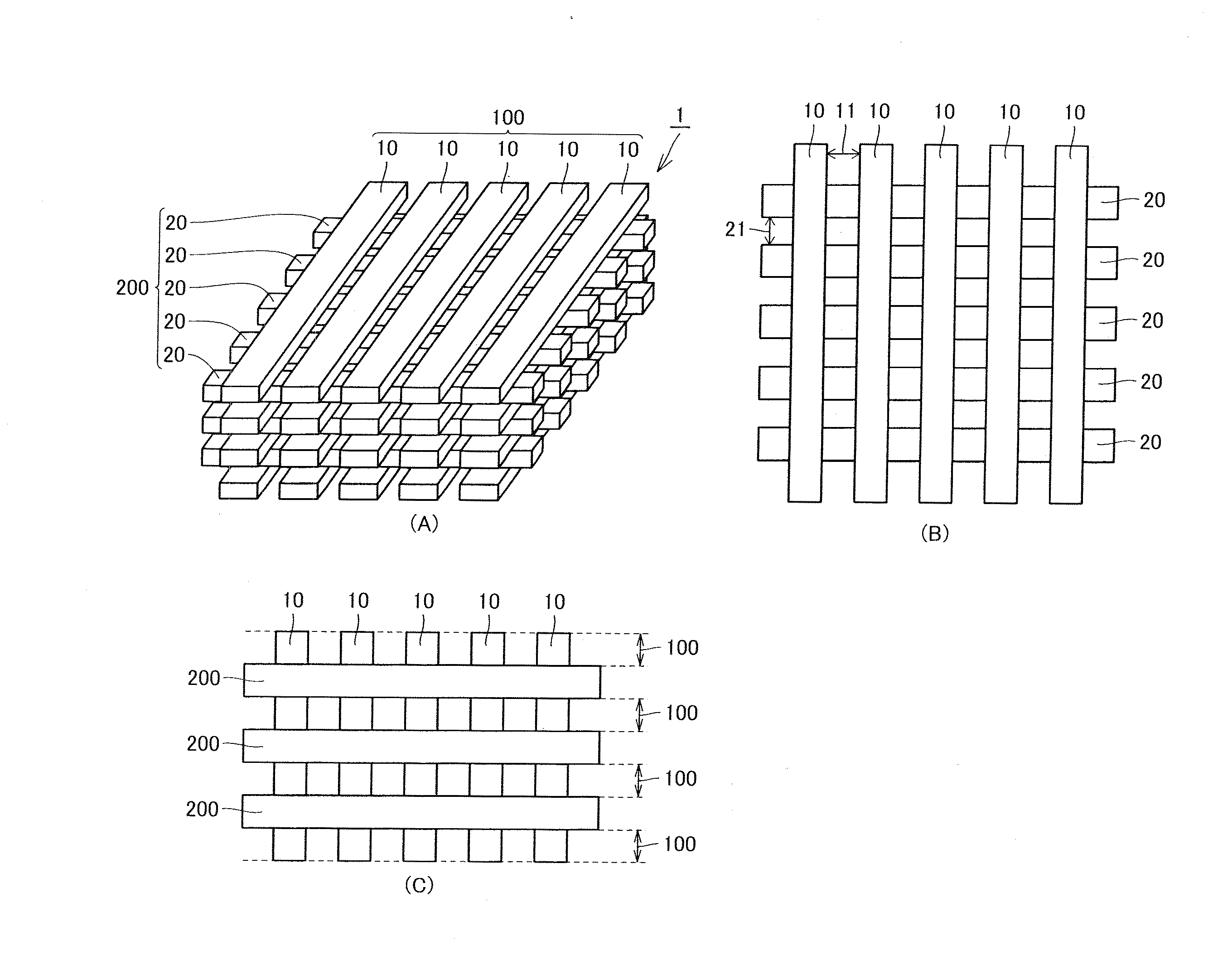
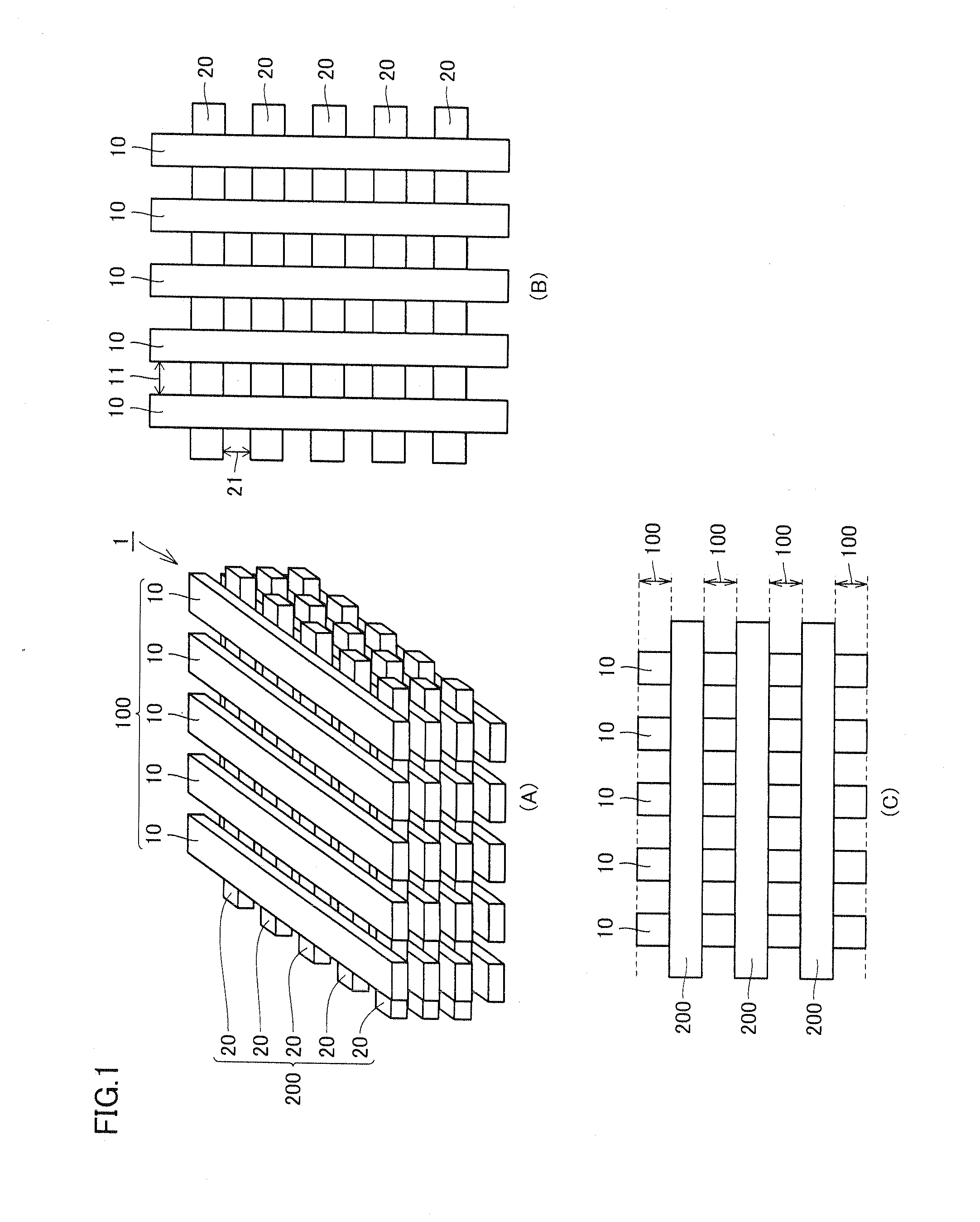
[0196]FIG. 9 shows schematic views of a preferable exemplary fuel cell stack according to the present embodiment, in which FIG. 9(A) is a perspective view thereof, FIG. 9(B) is a top view thereof, and FIG. 9(C) is a side view thereof.
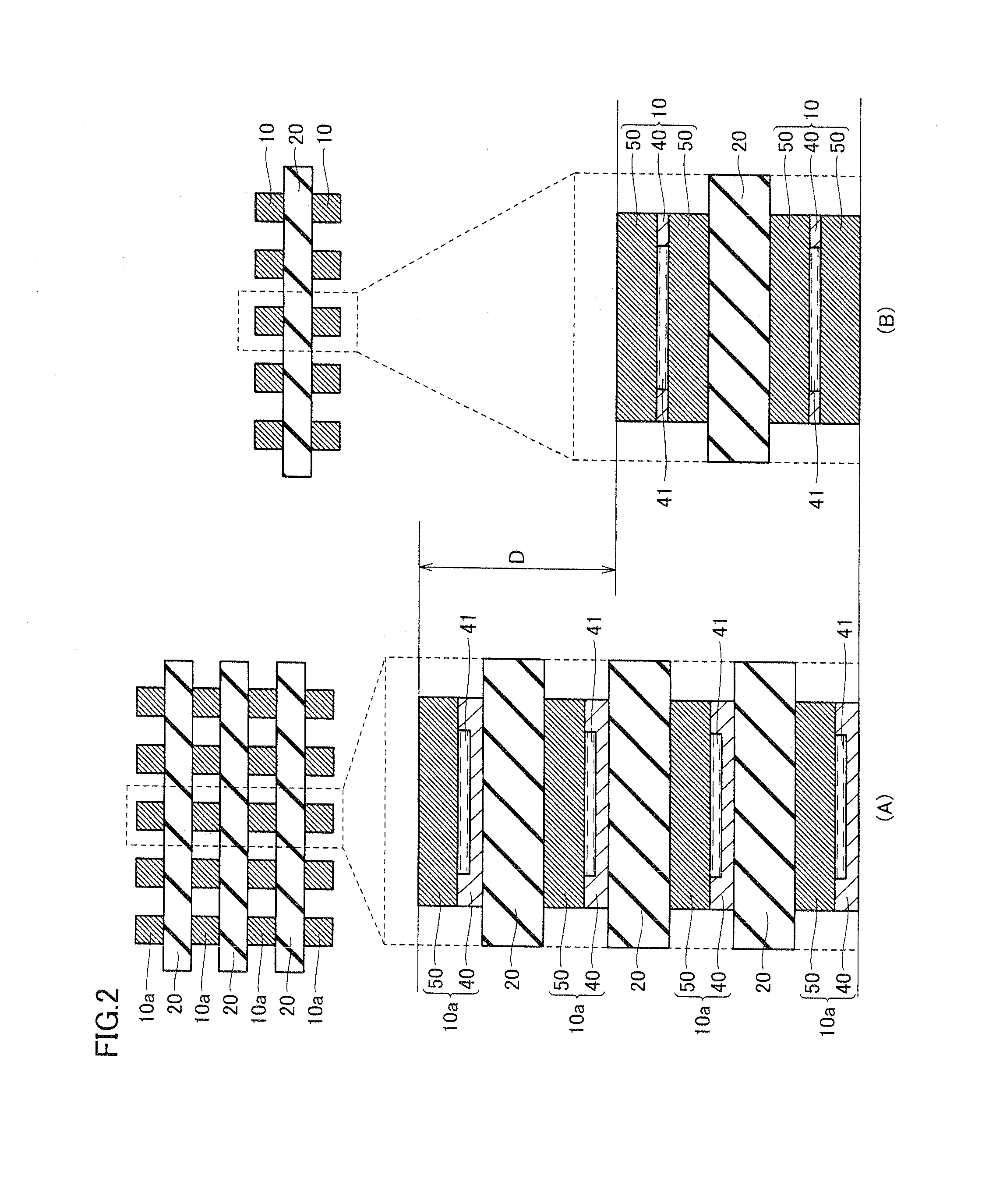
[0197]The structure of the fuel cell stack according to the present embodiment may be, for example, a structure as shown in FIG. 9. In the fuel cell stack shown in FIG. 9, the lowermost fuel cell layer 100a includes unit cells 10a instead of composite unit cells 10. Thus, in the fuel cell stack according to the present embodiment, one or more of the fuel cell layers may be fuel cell layer 100a in which unit cells 10a are arranged with a gap provided therebetween. The fuel cell stack with such a structure is preferably used in a case where the lower surface of the fuel cell stack is in contact with an electronic device.
[0198]Preferably, unit cells 10a having the single-surface unit cell structure that constitute the lowermost fuel cell layer 100a in the ...
embodiment 3
[0199]FIG. 10 shows schematic views of a preferable exemplary fuel cell stack according to the present embodiment, in which FIG. 10(A) is a perspective view thereof, FIG. 10(B) is a top view thereof, and FIG. 10(C) is a side view thereof.
[0200]The structure of the fuel cell stack according to the present embodiment may be, for example, a structure as shown in FIG. 10. The fuel cell stack shown in FIG. 10 has a structure in which the lowermost fuel cell layer is a fuel cell layer 100b made of a large-area unit cell. Thus, in the fuel cell stack according to the present embodiment, one or more of the fuel cell layers may be composed of a large-area unit cell. The fuel cell stack has a configuration preferably used in a case where its lower surface is in contact with an electronic device, as with the fuel cell stack according to Embodiment 2.
[0201]Preferably, the large-area unit cell constituting the lowermost fuel cell layer 100b in the fuel cell stack shown in FIG. 10 is arranged suc...
PUM
 Abstract
Description
Claims
Application Information