Method of measuring the flux of a soil gas

a technology of soil gas and flux, applied in the field of soil gas measurement, can solve the problems of affecting both the soil structure and the gas transport regime, prone to underestimating flux, and diffusivity models that perform better, so as to overcome or mitigate one or more disadvantages of known methods

Active Publication Date: 2012-02-09
EOSENSE INC
View PDF17 Cites 26 Cited by
  • Summary
  • Abstract
  • Description
  • Claims
  • Application Information

AI Technical Summary

Benefits of technology

[0011]It is an object of the present invention to provide a method of measuring the flux of a soil gas that overcomes or mitigates one or more disadvantages of known methods, or at least provides a useful alternative.
[0012]The method of the present invention provides the advantages of being easy to put in practice, requiring only a few pieces of equipment that are easy to deploy, and requiring little human intervention.

Problems solved by technology

The concentration gradient method requires the measurement of two or more concentrations at different depths in the soil profile and often involves disturbing the soil to install monitoring equipment.
This affects both the soil structure and the gas transport regime.
This method, however, typically underestimates fluxes because of improperly constrained diffusion coefficients or effective soil gas diffusivity values.
Unfortunately, diffusivity models tend to perform better in some soils than in others.
Aside from diffusivity, other limitations of the gradient approach include the intensiveness of sampling as several simultaneous concentration measurements are required for one flux calculation, frequent gas well installation challenges, the high degree of lateral variability in gas concentrations owing to subsurface heterogeneity, the need for post-processing of data, and the added error resulting from the multiple necessary steps of gas extraction, sample transport, and laboratory analysis.
Despite the advantages of chamber techniques (simplicity, commercial availability, real-time data), they have several important limitations.
Chambers are not suitable for use during winter where snow is present, particularly the permanent deployment types with moving external parts.
Commercially available systems are expensive and have been found to underestimate fluxes in certain cases and overestimate them in others.
There also exist design problems with static chambers in that the estimated flux can be affected by changes in atmospheric pressure as well as by buildup of fluxing gas in the chambers, causing fluxes to slow with time.
Other drawbacks include the inability to estimate fluxes from large portions of the soil surface and, in the case of the static chamber methods, the need to return and manually sample the gases built up in the chambers.
This latter problem makes a time intensive process that has the possibility for contamination and error.
This is a technique reserved for highly skilled specialists because it is mathematically complex, requires care in setting up stations, and requires significant data conditioning and post-processing.
To date, there is neither a uniform terminology nor a single methodology for the eddy covariance technique.
While the technique can return data on average gas fluxes from a large area (up to several square kilometers), the key assumptions that underlie the method expose obvious limitations.
Firstly, fluxes must be fully turbulent, and most of the net vertical transfer must be done by eddies, which means that data cannot be acquired under windless conditions in which eddies are not present, such as frequently occurs at night.
This means that areas outside the area of interest might be frequently unintentionally monitored.
Moreover, eddy covariance stations are extremely expensive to buy, deploy, and run, yet they still suffer from large temporal gaps in collected data.
Recent research has shown that the footprint is also a considerable drawback for industrial purposes, such as carbon capture and storage, because eddy covariance stations are not capable of resolving large magnitude emissions from limited areas.

Method used


Image

  • Method of measuring the flux of a soil gas
  • Method of measuring the flux of a soil gas
  • Method of measuring the flux of a soil gas

Examples


second embodiment

[0062]the present invention is now described. Reference is made to FIG. 3. In this embodiment, a known measurement technique is used to measure soil gas concentration data over a large spatial scale. This system of measurement uses a semi-permeable polyvinyl tube 36 connected to a recirculating pump 38 and a gas analyzer 40. The tube 36 allows unrestricted diffusion of the soil gas into its interior, where it is circulated in a closed loop, allowing the tube 36 to reach equilibrium with its surroundings quickly. After equilibrium has been reached, the soil gas may be drawn off the loop and sampled by the gas analyzer 40. Since the tube 36 is constantly in equilibrium with its surroundings, small spatial variation in soil gas concentrations are averaged by the circulating air inside the tube 36. This averaging gives a representative gas concentration for the entire area with which the tube 36 is in contact, rather than a point measurement. Soil gas diffusivity must be measured with a...

third embodiment

[0063]A third embodiment is now described, with reference to FIG. 4. In the present embodiment, the single-point Flux Solution is coupled to a simultaneous measurement of soil gas diffusivity. Risk, in published U.S. patent application Ser. No. 10 / 419,082, describes an automated method and system for use in determining diffusivity values in-situ. However, rather than the described technique relying on a continuous flow membrane probe buried in the soil and coupled to an above ground control / measurement system, the probe 42 of the present embodiment is deployed at the soil-atmosphere interface to measure fluctuations in soil gas concentration, while still connected to a similar above ground control / measurement system 44. Diffusivity need be measured only infrequently, such as once per day, due to the slow changes in soil moisture that influences the diffusivity magnitude. This leaves significant periods where the probe 42, which is now a dual-purpose probe capable of both measuring s...


PUM


Abstract

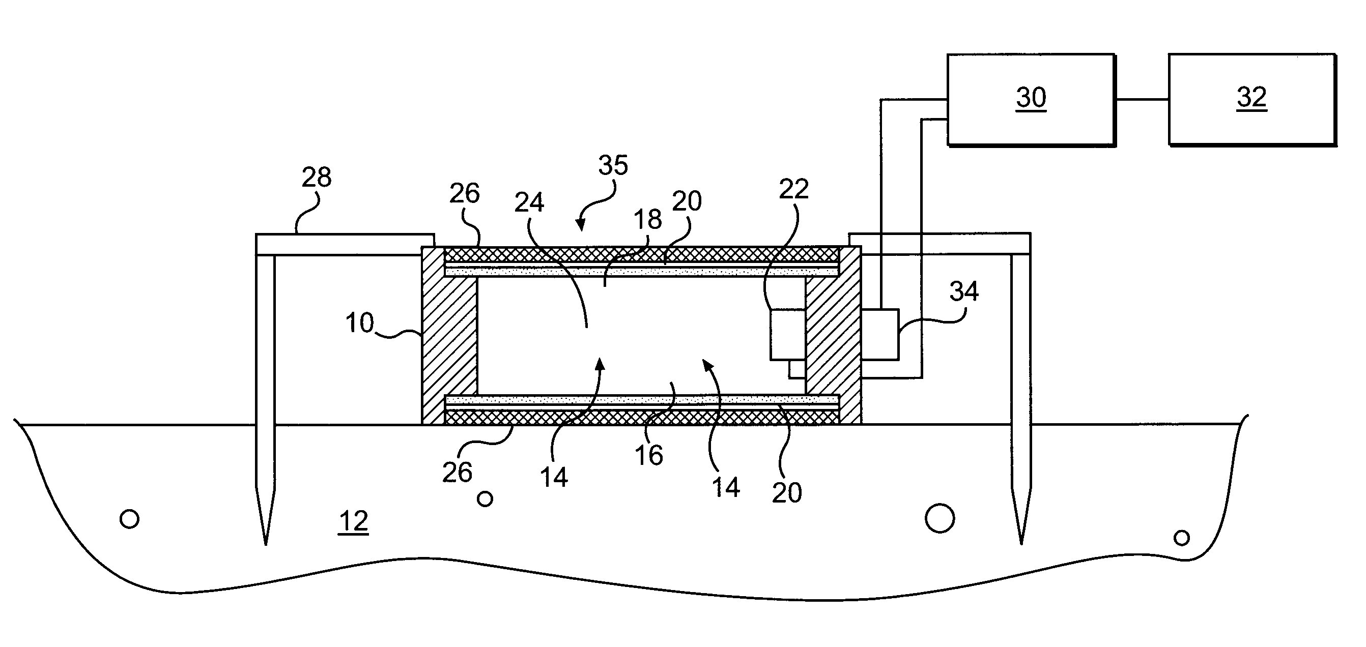
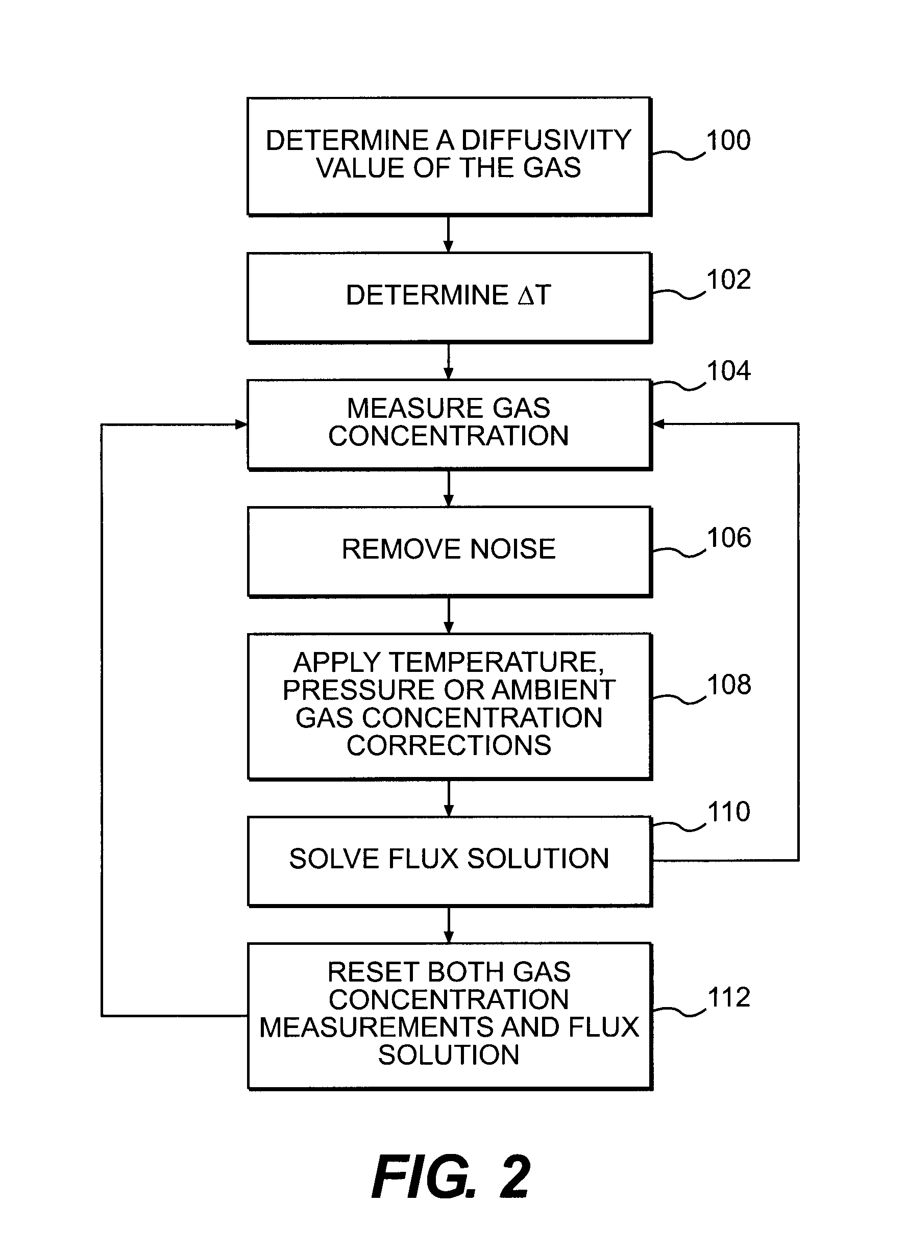
A method for determining a flux of a gas contained in a medium through a boundary of the medium comprises 1) measuring at least twice with a probe a concentration C of the gas over a time interval Δt and 2) determining the flux of the gas using the following mathematical equation: (I) where F is the gas flux, D is the diffusivity value and ΔC is a variation in the gas concentration during the time interval Δt. The probe is placed proximate the boundary. The probe has a gas inlet, a cavity, a gas concentration sensor and a membrane. Each element is in fluid communication with each other so that the gas flows from the gas inlet through the membrane and contacts the gas concentration sensor.F=(D∂C(z,t)∂z)z=0=DΔCπΔt(I)

Description

FIELD OF THE INVENTION[0001]The present invention relates generally to the field of soil gas measurement. More specifically, the invention relates to a method of measuring the flux of a soil gas.BACKGROUND OF THE INVENTION[0002]Measurement and monitoring of gas fluxes is a common practice in many areas of the Earth. For example, in volcanically active regions, the measurement and monitoring of gas fluxes can be an indicator of changes in volcanic activity and could even be critical in saving human lives in the event that CO2 gases are built up in the soil and have the potential for catastrophic release. In the oil industry, measurements of volatile hydrocarbon emissions can be a non-intrusive and inexpensive way of finding potential hydrocarbon deposits. At contaminated sites, flux measurements can either be used to map out the extent and severity of the contamination or can be implemented to determine natural attenuation rates. Moreover, flux measurements are also used extensively ...

Claims


Application Information

Patent Timeline
Patent Type & Authority Applications(United States)
IPC IPC(8): G06F19/00G01V9/00
CPCG01N1/2205G01N1/2294G01N2013/003G01V9/007
Inventor RISK, DAVID A.BELTRAMI, HUGO J.NICKERSON, NICHOLAS R.MCARTHUR, GORDON
Owner EOSENSE INC
Why Eureka
Try Eureka