Laser light source apparatus

a technology of laser light source and light source body, which is applied in the direction of lighting and heating apparatus, instruments, lighting support devices, etc., can solve the problems of large heat generation at the semiconductor and relatively low heat resistance of cast materials, and achieves high heat resistance, lower adhesion temperature, and high heat resistance.

Inactive Publication Date: 2012-02-23
PANASONIC CORP
View PDF3 Cites 29 Cited by
  • Summary
  • Abstract
  • Description
  • Claims
  • Application Information

AI Technical Summary

Benefits of technology

[0011]In view of the above, the present invention provides a laser light source apparatus including a semiconductor laser emitting laser light; a base supporting the semiconductor laser; and a mounting member provided between the base and the semiconductor laser. In the laser light source apparatus, the semiconductor laser and the mounting member are fixedly attached by a thermally adhesive material; the adhesive material has a lower adhesion temperature than an assurance temperature of the semiconductor laser and a higher heat resistance than an operation temperature of the semiconductor laser; and the mounting member is formed of a material having a higher h...

Problems solved by technology

In this case, output of a semiconductor laser needs to be high, in view of conversion loss at a laser medium and a wavelength conversion element, t...

Method used


Image

  • Laser light source apparatus
  • Laser light source apparatus
  • Laser light source apparatus

Examples


embodiments

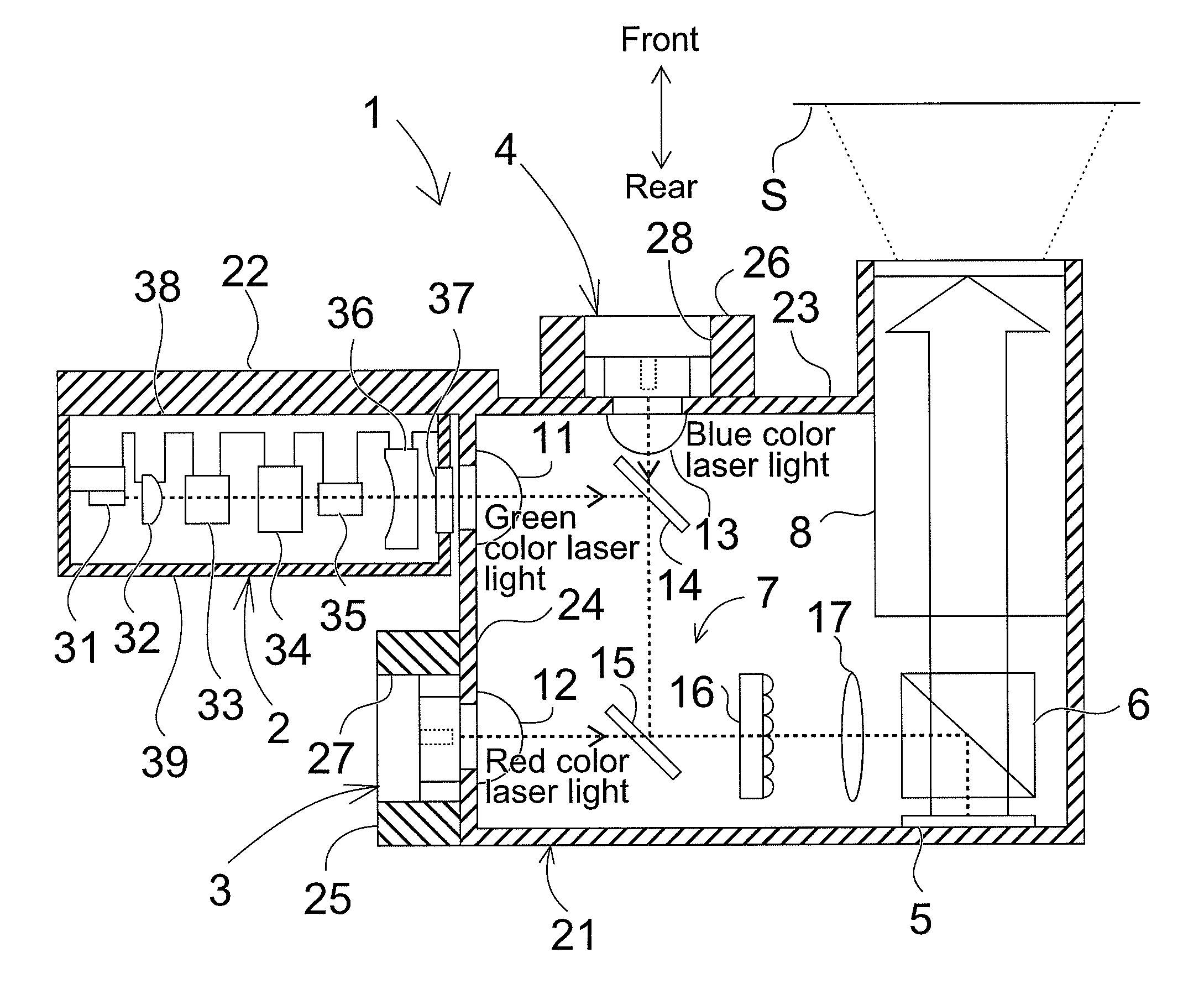
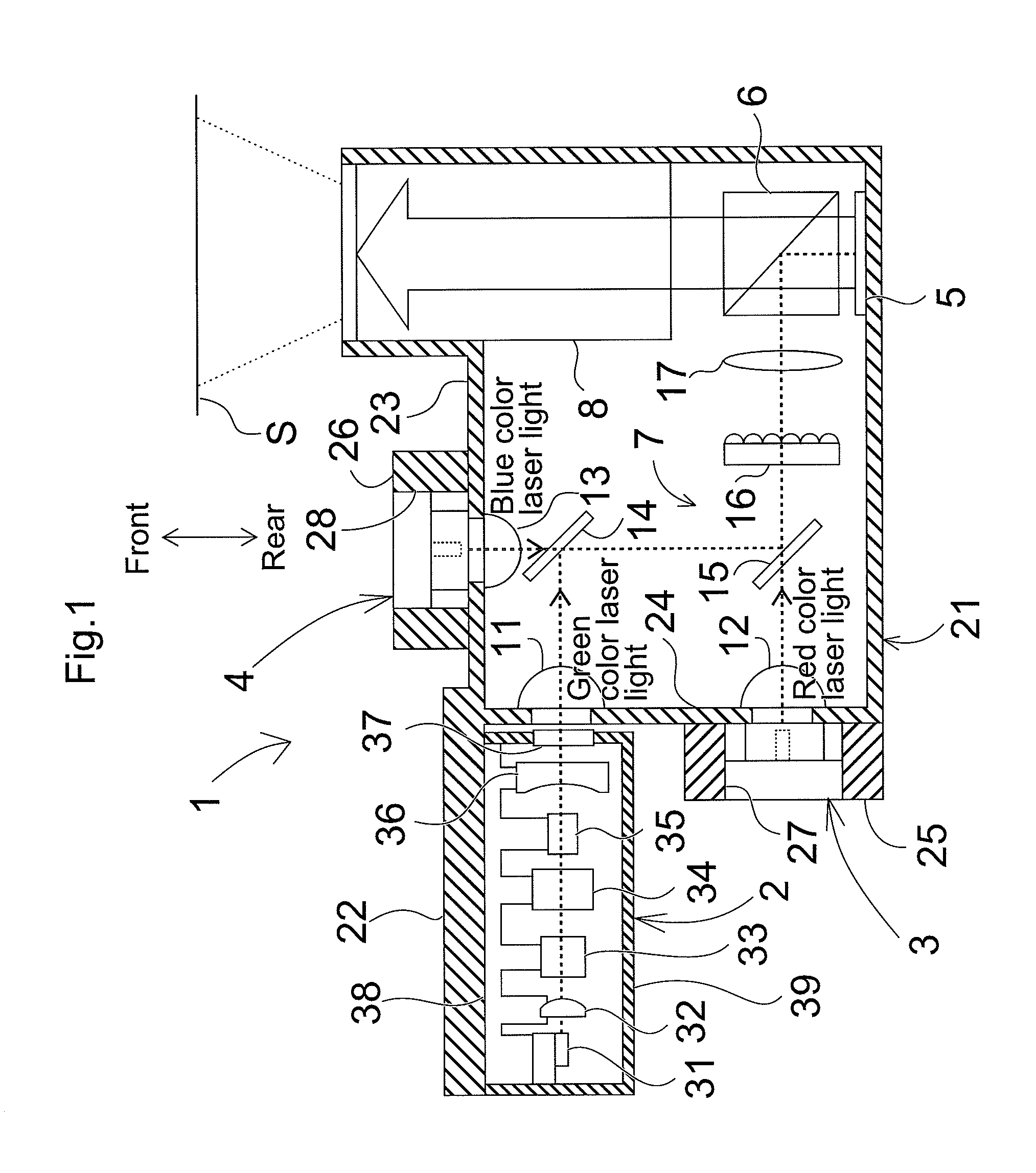
[0022]The embodiments of the present invention are explained below with reference to the drawings. FIG. 1 is a schematic view of a configuration of an image display apparatus 1 according to a present invention. The image display apparatus 1, which projects and displays a predetermined image on a screen, has a green color laser light source apparatus 2 emitting green color laser light; a red color laser light source apparatus 3 emitting red color laser light; a blue color laser light source apparatus 4 emitting blue color laser light; and an LCD-reflective spatial light modulator 5 modulating the laser light emitted from each of the laser light source apparatuses 2 to 4, according to an image signal; a polarization beam splitter 6 reflecting the laser light emitted from each of the laser light source apparatuses 2 to 4 and radiating the light onto the spatial light modulator 5, and transmitting the modulated laser light emitted from the spatial light modulator 5; a relay optical syst...


PUM


Abstract

In order to reduce manufacturing cost of a base supporting a semiconductor laser, without deteriorating accuracy of mounting of the semiconductor laser, a mounting member is provided between the base supporting the semiconductor laser and the semiconductor laser; and the semiconductor laser and the base are fixedly attached with heat-cured silver paste. The silver paste has a lower curing temperature than an assurance temperature of the semiconductor laser, and a higher heat resistance than an operation temperature of the semiconductor laser. The mounting member is formed of a material having a higher heat resistance than the curing temperature of the silver paste.

Description

CROSS-REFERENCE TO RELATED APPLICATIONS[0001]The present application claims priority under 35 U.S.C. §119 of Japanese Application No. 2010-186234 filed on Aug. 23, 2010, the disclosure of which is expressly incorporated by reference herein in its entirety.BACKGROUND OF THE INVENTION[0002]1. Field of the Invention[0003]The present invention relates to a laser light source apparatus using a semiconductor laser, specifically a laser light source apparatus used as a light source of an image display apparatus.[0004]2. Description of Related Art[0005]Technology recently drawing attention employs a semiconductor laser as a light source of an image display apparatus. Compared with mercury lamps conventionally widely used in image display apparatuses, the semiconductor laser has a variety of advantages, including good color reproducibility, instant light up, long life, high efficiency and reduction in power consumption, and easy downsizing.[0006]For such a laser light source apparatus used i...

Claims


Application Information

Patent Timeline
IPC IPC(8): G02B27/20F21V21/00
CPCG02B27/20G03B21/2033H01S3/109H01S5/02208G03B21/204H01S5/4093H04N9/3111H04N9/3161H04N9/3173H01S5/02252H01S5/02326
Inventor HATASE, YUICHISUYAMA, KOHEIENOMOTO, HIROFUMIOSADA, AKINORIKITAOKA, YOSHITAKA
Owner PANASONIC CORP
Why Eureka
Try Eureka