Light source unit

a technology of light source and light guide, which is applied in the direction of instruments, lighting and heating apparatus, fibre light guides, etc., can solve the problems of inability to emit light from a light source, small illumination of light emitted from the light guide, etc., and achieves high efficiency, high degree of design freedom, and more surely inhibited

Active Publication Date: 2012-03-01
USHIO DENKI KK
View PDF10 Cites 9 Cited by
  • Summary
  • Abstract
  • Description
  • Claims
  • Application Information

AI Technical Summary

Benefits of technology

[0030]In the light source unit according to the present invention, the liquid core fiber is used as the light guide, the infrared cut filter is provided, and the heat insulating material portion formed of the heat insulating material is interposed between the light shielding body and the light guide holding portion, whereby the light shielding body and the light guide holding portion are thermally insulated from each other, so that infrared rays are inhibited from being struck on the liquid core fiber making up the light guide to inhibit the liquid core fiber from being heated by the infrared rays. In addition, even when the light shielding body is heated to a high temperature by receiving the light from the light source, the heat of the light shielding body is inhibited from being transmitted to the light guide holding portion by transmitting the heat through the members making up this light source unit, so that the light guide can be inhibited from being heated by the light shielding body heated to the high temperature.
[0031]Accordingly, according to the light source unit of the present invention, the liquid core fiber making up the light guide can be inhibited from being overheated when the liquid core fiber is used as the light guide, thereby supplying light without causing evils attributed to the overheating of the liquid core fiber.
[0032]In the light source unit according to the present invention, the support for light shielding body is formed of the heat insulating material, whereby the support for light shielding body has an action that the light shielding body and the light guide holding portion are thermally insulated from each other in addition to the action that the light shielding body is supported and fixed to the casing, so that the heat of the light shielding body is inhibited from being transferred to the casing through the member supporting the light shielding body. Accordingly, there is no need to separately provide an exclusive member for supporting the light shielding body and an exclusive member for thermally insulating the light shielding body and the light guide holding portion in the casing from each other, so that a high degree of freedom of design is obtained.
[0033]In the light source unit according to the present invention, the cooling air inlet and the cooling air outlet are provided in the casing to cool the light shielding body by cooling air from the cooling fan, thereby inhibiting the light shielding body receiving the light from the light source from raising its temperature, so that the liquid core fiber can be still more surely inhibited from being overheated.
[0034]In the light source unit according to the present invention, the infrared cut filter is provided, whereby infrared rays are inhibited from being struck on the liquid core fiber making up the light guide to inhibit the liquid core fiber from being heated due to the incidence of the infrared rays. In addition, the unit is so constructed that parallel light or substantially parallel light is projected from the concave mirror of the light source, and the condenser lens is provided, so that even when the infrared cut filter has the infrared reflecting layer formed of the multi-layer reflection film, and transmitted light of the light struck at a large incident angle causes a wavelength shift that the spectral distribution thereof is shifted on a short wavelength side because of its structure, the concave mirror inhibits the light large in incident angle from being struck on the infrared cut filter. In addition, since the light high in degree of parallelization is condensed by the condenser lens, the light is incident on the light guide at a high efficiency, and thus the occurrence of the evils attributed to the use of the infrared cut filter equipped with the multi-layer reflection film can be inhibited. After all, when the liquid core fiber is used as the light guide, the liquid core fiber making up the light guide can be inhibited from being heated due to the irradiation of the infrared rays without causing any evil.
[0035]Further, the spheroidal mirror is used as the concave mirror, whereby there is no need to make the aperture of the concave mirror large for obtaining high light intensity in outgoing light from the light guide because this spheroidal mirror can converge the light emitted from the discharge lamp at a high efficiency and project the light high in degree of parallelization, so that a high degree of freedom of design can be obtained to easily miniaturize the unit.

Problems solved by technology

However, sufficient flexural property is not achieved by the quartz fiber, and the total reflection angle of the quartz fiber is small, so that such a light source unit involves a problem that when the light guide is used in a flexed state, the illuminance of light emitted from the light guide becomes small.
However, when the liquid core fiber is used as a light guide in the light source unit, there is a problem that light from a light source is not emitted from a light outgoing port of the light guide during its actuation.

Method used


Image

  • Light source unit
  • Light source unit
  • Light source unit

Examples


experimental example 1

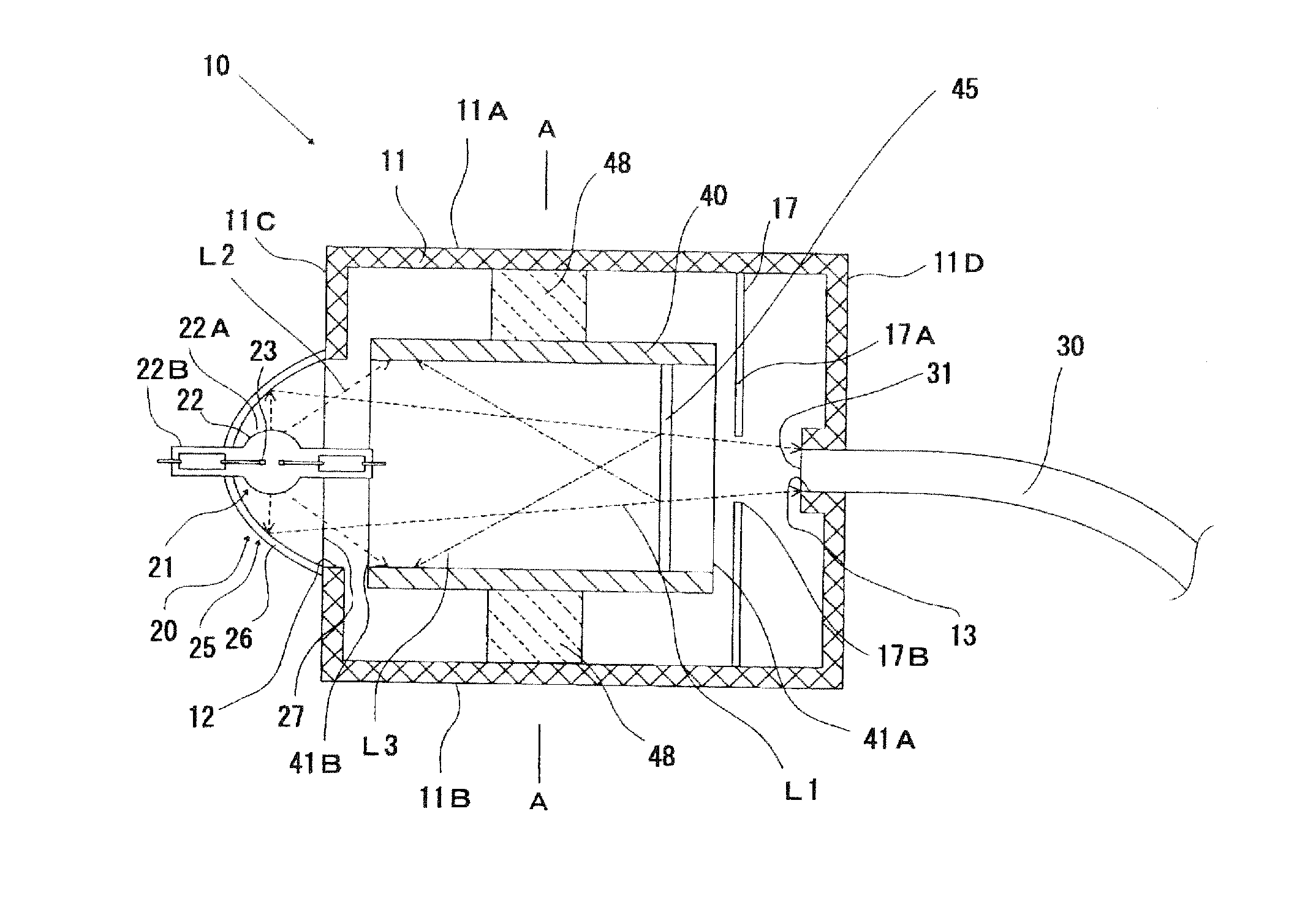
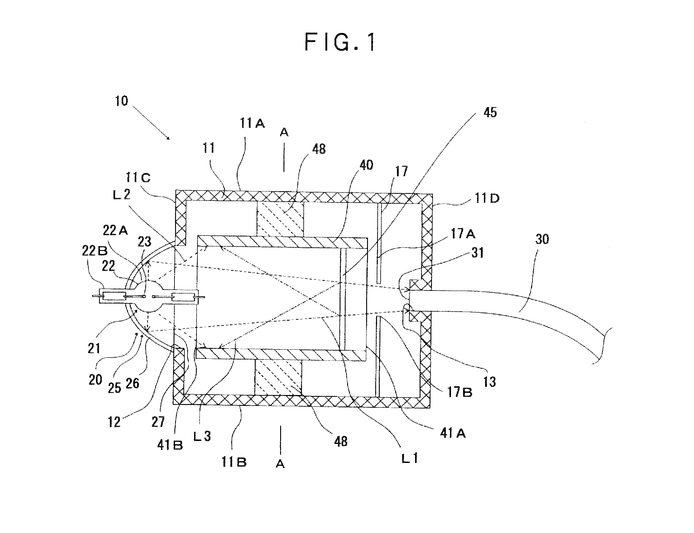
[0086]An light source unit (hereinafter also referred to as “light source unit (1)”) having the construction illustrated in FIG. 1 and FIG. 2 was fabricated.

[0087]A light source making up this light source unit (1) is composed of an extra-high pressure mercury lamp whose rated power consumption is 130 W and a converging mirror reflecting and converging light within a wavelength range up to 800 nm, and its maximum incident angle of light at a focal point is 13.5°.

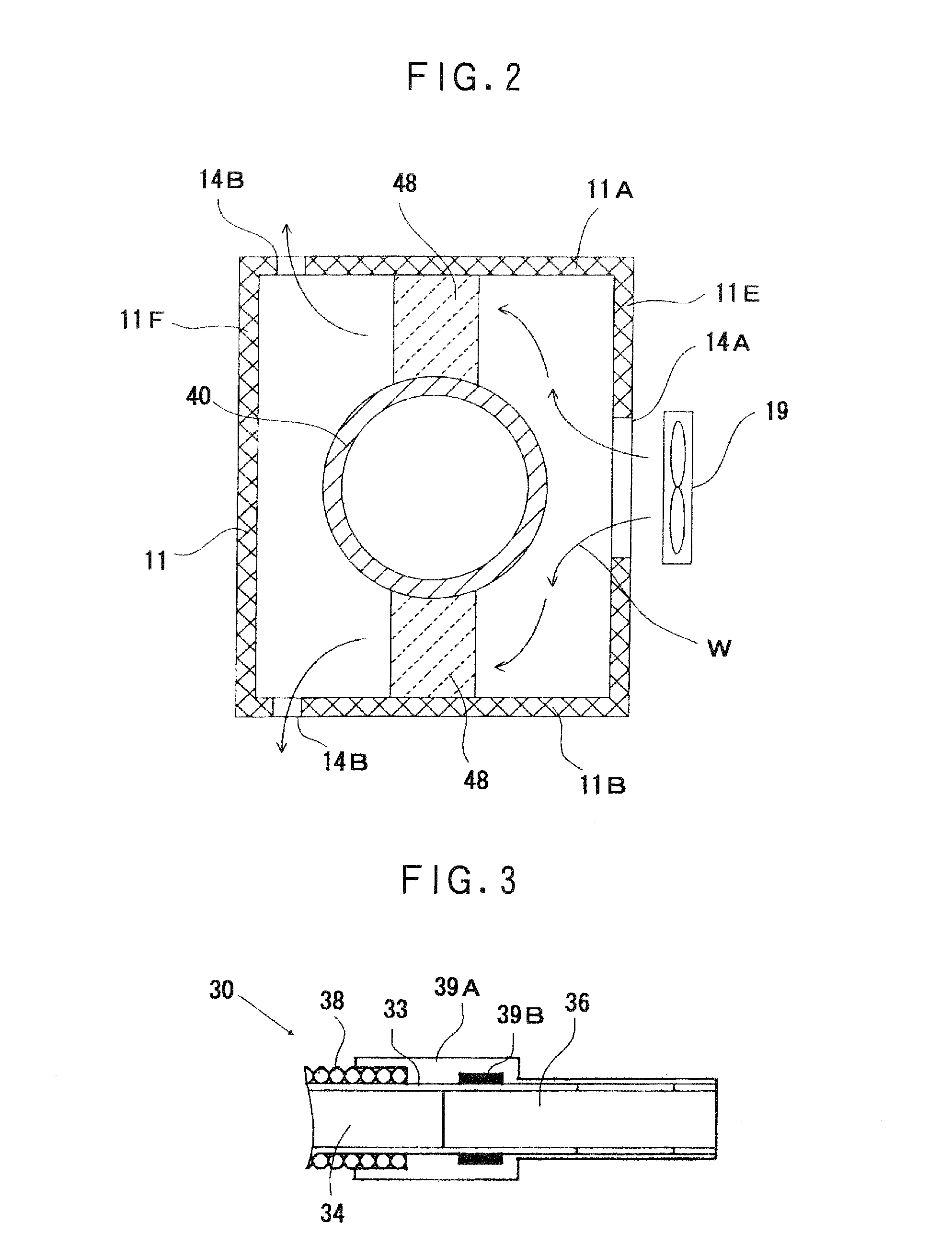
[0088]As a light guide, was used a liquid core fiber manufactured by LUMATEC CO.

[0089]A casing is made of aluminum (heat conductivity: 138 [W·m−1·K−1]), and the light source and the light guide are supported by this casing in such a manner that a clearance between them, i.e., a clearance between a light projecting port in the light source and a light incident port in the light guide is 100 mm.

[0090]A light shielding body is made of aluminum, and as an infrared cut filter, was used a filter that transmits light having a wavel...

experimental example 2

[0095]An light source unit (hereinafter also referred to as “light source unit (2)”) having the same construction as in the light source unit (1) according to Experimental Example 1 except that no cooling fan was used was fabricated, and regarding the light source unit (2) fabricated, a temperature of the light incident port of the light guide was measured after 8 hours elapsed from the beginning of the actuation in the same manner as in Experimental Example 1. A result is shown in Table 1.

experimental example 3

[0133]An light source unit (hereinafter also referred to as “light source unit (3)”) was fabricated according to FIG. 4, and a light source unit (hereinafter also referred to as “comparative light source unit (3)”) having the same construction as in the light source unit (3) except that no condenser lens was provided was fabricated.

[0134]As a light source making up the light source unit (3) and comparative light source unit (3) fabricated, was used the following. An extra-high pressure mercury lamp whose rated power consumption is 130 W was used as a discharge lamp, a spheroidal mirror which reflects and converges light within a wavelength range up to 800 nm, the clearance between the second focal point and the light projecting port of which is 100 mm, was used as a concave mirror, and these were arranged in such a manner that the first focal point of the concave mirror (spheroidal mirror) is located at the position of a luminescent spot of the discharge lamp (extra-high pressure me...


PUM


Abstract

The invention provides a light source unit using a liquid core fiber as a light guide, by which the liquid core fiber is inhibited from being overheated, and a light source unit by which an infrared cut filter having a multi-layer reflection film can prevent infrared rays from being introduced into a liquid core fiber, and its miniaturization can be made without causing evils.
The first light source is equipped with a light source having a discharge lamp and a converging mirror, and a light guide formed of a liquid core fiber, wherein the light source and the light guide are held in a casing made of a metal, an infrared cut filter is provided in a cylindrical light shielding body surrounding an optical path in the interior of the casing, and the light shielding body and the light guide holding portion are thermally insulated from each other by a heat insulating material portion.
The second light source unit is equipped with a light source having a discharge lamp and a concave mirror projecting parallel light or substantially parallel light, and a light guide formed of a liquid core fiber, wherein an infrared cut filter having an infrared reflecting layer formed of a multi-layer reflection film is provided on an optical path, and a condenser lens is provided at a more forward position than the infrared cut filter.

Description

TECHNICAL FIELD[0001]The present invention relates to a light source unit, more particularly to a light source unit used for supplying lighting light to, for example, a biomicroscope.BACKGROUND ART[0002]As a certain kind of light source unit used for supplying lighting light to, for example, an endoscope, has heretofore been mentioned a unit equipped with a light source 20 having a discharge lamp 21 and a converging mirror 25 converging light from the discharge lamp 21, and a light guide 52, on which the light from the light source 20 is incident, as illustrated in FIG. 5, and having a construction that these light source 20 and light guide 52 are held and fixed at respective predetermined positions in a casing 11, the light from the discharge lamp 21 reflected on the converging mirror 25 is struck on the light guide 52 by condensing the light at a condensing point located at an arrangement position of a light incident port 53 of the light guide 52, and the light is guided by this l...

Claims


Application Information

Patent Timeline
Patent Type & Authority Applications(United States)
IPC IPC(8): F21V29/00F21V8/00F21V7/00
CPCA61B1/00126A61B1/0646G02B2006/0325A61B1/128G02B6/0006A61B1/0669
Inventor NAKABAYASHI, HITOSHIMORIMOTO, AKIHISAIGUCHI, TAKEHIKO
Owner USHIO DENKI KK
Why Eureka
Try Eureka