Optical system for high resolution thermal melt detection

Inactive Publication Date: 2012-03-01
CANON US LIFE SCIENCES INC
View PDF7 Cites 40 Cited by
  • Summary
  • Abstract
  • Description
  • Claims
  • Application Information

AI Technical Summary

Benefits of technology

[0016]Using a 2 dimensional CMOS or CCD sensor to image a fluorescence source is known in biological studies. Usually a microscope lens is used to image the fluorescence source into scientific CMOS/CCD sensor. In accordance with aspects of the present invention, improved imaging an

Problems solved by technology

Moreover, the costs of such imaging systems are a significant portion o

Method used


Image

  • Optical system for high resolution thermal melt detection
  • Optical system for high resolution thermal melt detection
  • Optical system for high resolution thermal melt detection

Examples


Embodiment Construction

[0057]Systems for nucleic acid analyses using microfluidic chips with one or more micro-channels, such as the system described in the aforementioned '230 publication, the '560 patent, and the real-time PCR architecture described in the aforementioned '124 patent, include an image sensor (or optical imaging system) for detecting optically-detectable characteristics of a sample flowing through a micro-channel, such as amplification products and flow rate of the test solution. Test solution flowing through each micro-channel may be in the form of discrete boluses of sample solution separated by carrier fluid, as described in the '124 patent.

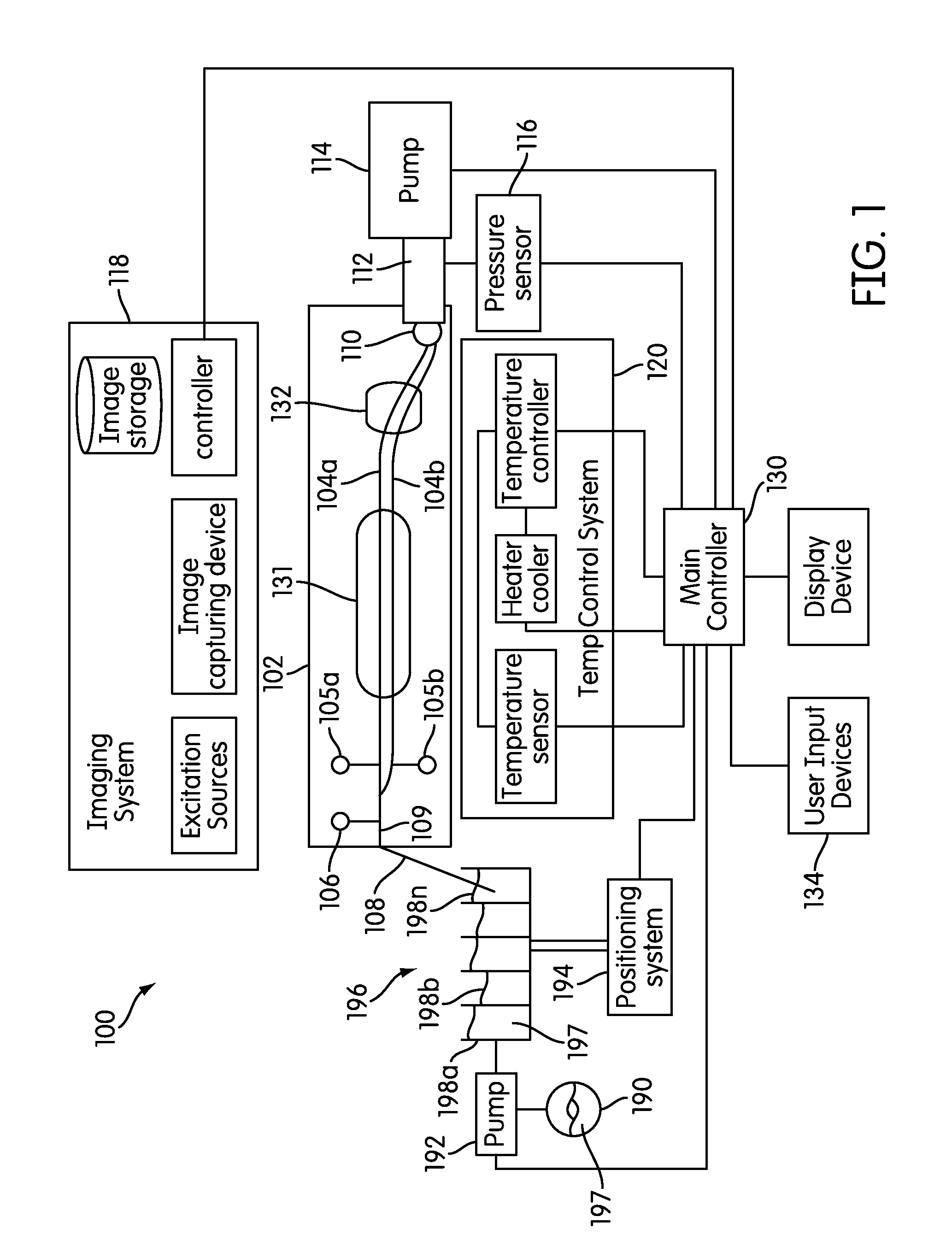
[0058]FIG. 1 is a block diagram illustrating a system 100 for rapid serial processing of multiple nucleic acid assays that can be configured to embody various aspects of the invention. System 100 may include a microfluidic device 102. Microfluidic device 102 may include one or more microfluidic channels 104. In the examples shown, device 102 include...


PUM

PropertyMeasurementUnit
Frequencyaaaaaaaaaa
Temperatureaaaaaaaaaa
Coloraaaaaaaaaa

Abstract

This invention relates to systems and methods for imaging sample materials within a microfluidic device during an assay reaction process. In accordance with certain aspects of the invention, images are formed with a pixel array and a region of interest (“ROI”) is defined within the pixel array. Image values, such as fluorescent intensity, can be computed as averages of individual pixel values within the ROI. Where the ROI is subject to non-uniform conditions, such as non-uniform heating, the ROI can be divided into sub-ROIs which are sufficiently small that the condition is uniform within the sub-ROI.

Description

CROSS-REFERENCE TO RELATED APPLICATION[0001]This application claims the benefit of priority to U.S. Provisional Application No. 61 / 378,471, filed Aug. 31, 2010, the disclosure of which is hereby incorporated by reference in its entirety.BACKGROUND[0002]1. Field of the Invention[0003]This invention relates to systems and methods for imaging sample materials within a microfluidic device during an assay reaction process.[0004]2. Discussion of the Background[0005]The detection of nucleic acids is central to medicine, forensic science, industrial processing, crop and animal breeding, and many other fields. The ability to detect disease conditions (e.g., cancer), infectious organisms (e.g., HIV), genetic lineage, genetic markers, and the like, is ubiquitous technology for disease diagnosis and prognosis, marker assisted selection, correct identification of crime scene features, the ability to propagate industrial organisms and many other techniques. Determination of the integrity of a nuc...

Claims


Application Information

Patent Timeline
IPC IPC(8): H04N7/18C12M1/34
CPCH04N7/183B01L3/502715C12Q1/686B01L3/5027B01L2400/049C12Q1/68G01N21/6456B01L7/52B01L2300/0816C12Q2565/607C12Q2565/619C12Q2565/629
Inventor LIANG, HONGYEHASSON, KENTON C.
Owner CANON US LIFE SCIENCES INC
Why Eureka
Try Eureka