Cutting method by sandblasting

a cutting method and sandblasting technology, applied in the field of sandblasting, can solve the problems of inconvenient processing methods, inefficient use of resources, and above-described resist formation by lithography, and achieve the effects of improving the yield of cutting out, high fraction defect, and reducing the work of finishing processing and the like to be performed thereafter

Active Publication Date: 2012-03-01
FUJI MFG CO LTD
View PDF7 Cites 11 Cited by
  • Summary
  • Abstract
  • Description
  • Claims
  • Application Information

AI Technical Summary

Benefits of technology

[0039]In contrast to this, with the method of the present invention, since a cut is made from both surfaces, a side surface formed in a cut hole is at almost right angles with respect to front and back surfaces. Thus, the work of finish processing and the like to be performed thereafter can be reduced, and a machining allowance t (see FIG. 2D) can be reduced. This makes it possible to improve yield in cutting out, and, when a through-hole is formed, to accurately form a through-hole having a small diameter or a slit having a small width by sandblasting.
[0040]In particular, in the case where the workpiece is made of a hard, brittle material such as glass, ceramic, or a silicon wafer, when an attempt to form a through-hole by projecting abrasive against one surface is made, the occurrence of chipping increases. This leads to a high fraction defective. However, in the case where abrasive is projected against both surfaces as in the present invention, the occurrence of such chipping can be greatly reduced.
[0041]The formation position of the resist on the front surface of a workpiece and the formation position of the resist on the back surface thereof can be aligned with each other with high accuracy by using a transparent plate as the workpiece, taking an image of the resist formed on the front side with, for example, a CCD camera or the like by using a known image recognition technique, and forming a resist on the back side in accordance with coordinates found from the taken image.
[0042]Further, in the case where the projection of abrasive in the cutting step is simultaneously performed against the front and back surfaces of a workpiece, processing time can be further shortened.

Problems solved by technology

However, these processing methods are not suitable for processing a surface to be processed having a relatively large area.
Thus, the above-described resist formation by lithography does not efficiently use resources, and is not economical.
Thus, a lot of initial investments are needed.
As a result, the number of steps for obtaining a sandblast-resistant resist can be greatly reduced, and a device for placing a photomask and a cleaning tank become unnecessary with the reduction in the number of steps.
Due to this and the like, resist formation takes a long time.
Also, as described with reference to FIGS. 3A to 3D, it is difficult to form a fine through-hole with high accuracy.

Method used


Image

  • Cutting method by sandblasting
  • Cutting method by sandblasting
  • Cutting method by sandblasting

Examples


example

[0085]An example of cutting according to the method of the present invention will be described below.

(Workpiece)

[0086]a glass plate of length 90 mm×width 90 mm×thickness 0.7 mm.

(Details of Processing)

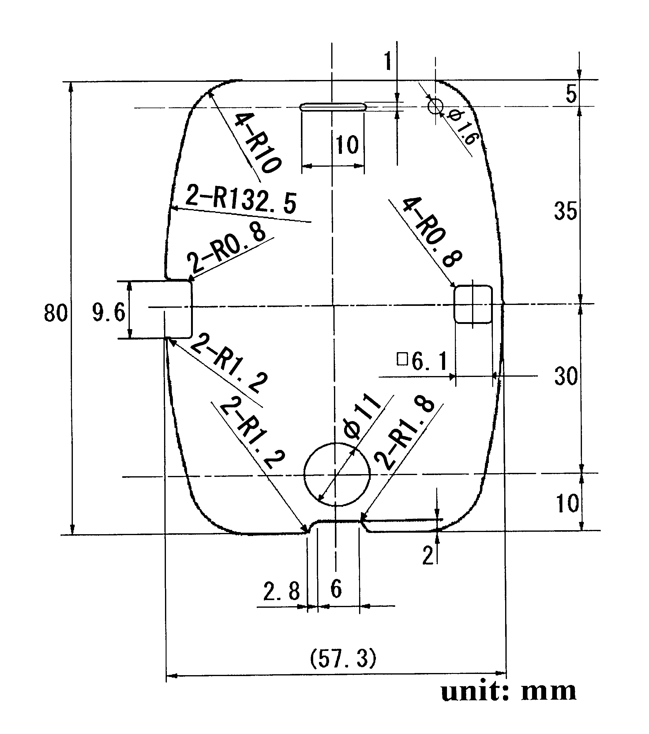
[0087]The above-described glass plate was processed in a test pattern shown in FIG. 4. Further, a through slit of width 0.8 mm×length 10 mm and a through-hole having a diameter of 0.8 mm were formed in a similar glass plate.

(Resist Formation)

(1) Resist Ink

[0088]As resist ink, “UVink F-200” manufactured by Mimaki Engineering Co., Ltd. was used. The composition of this resist ink is shown in Table 1.

TABLE 1Composition of Resist InkIngredientContent (%)Tetrahydrofurfuryl Acrylate10-30Isooctyl Acrylate10-25Isobornyl Acrylate10-25Modified Amine Acrylate Oligomer 5-20Aliphatic Urethane Acrylate10-201,6-Hexanediol Diacrylate 1-10Benzophenone 1-10Diphenyl(2,4,6-Trimethylbenzoyl)Phosphine Oxide 1-10Acrylic Ester1-5

(2) Method for Forming Resist

[0089]As a printing apparatus, an inkjet printer havi...


PUM

PropertyMeasurementUnit
thicknessaaaaaaaaaa
angleaaaaaaaaaa
lengthaaaaaaaaaa

Abstract

A cutting method by sandblasting in which cutting through of a workpiece and/or formation of a through-hole in the workpiece are/is performed by forming a resist on a plate-shaped workpiece and projecting abrasive against the workpiece to cut a portion of the workpiece where no resist is formed, comprises the steps of: forming the resist in a predetermined pattern on a front surface and a back surface of the workpiece symmetrically between the front and back by inkjet printing, and projecting the abrasive against each of the front and back surfaces of the workpiece to make a cut from the front surface side communicate with a cut from a back side at an approximately intermediate position of a thickness of the workpiece.

Description

BACKGROUND OF THE INVENTION[0001]1. Field of the Invention[0002]The present invention relates to a cutting method by sandblasting, and more specifically to a cutting method by sandblasting suitable for the cutting out of parts from a plate-shaped workpiece and the formation of a through-hole on a plate-shaped workpiece.[0003]It should be noted that in the present invention, the term a through “hole” also refers to “groove.”[0004]2. Description of the Related Art[0005]In general, the following kinds of processing are performed by cutting:[0006]cutting out (dicing) a cover glass used in a display screen of a mobile phone, cutting through thin-sheet glass for a touchscreen mounted on a liquid crystal display screen or the like, cutting out parts from a plate-shaped workpiece such as other glass, ceramic, metal, a silicon wafer, or the like, and forming a hole or groove on such a workpiece.[0007]Examples of such cutting include cutting out or hole making performed using a grinding wheel...

Claims


Application Information

Patent Timeline
Patent Type & Authority Applications(United States)
IPC IPC(8): B24C1/04
CPCB24C1/045B24C1/04
Inventor MASE, KEIJIISHIBASHI, SHOZO
Owner FUJI MFG CO LTD
Why Eureka
Try Eureka