
Endoscopic light guide and endoscope having the same

Inactive Publication Date: 2012-03-01
FUJIFILM CORP
View PDF6 Cites 7 Cited by
  • Summary
  • Abstract
  • Description
  • Claims
  • Application Information

AI Technical Summary

Benefits of technology

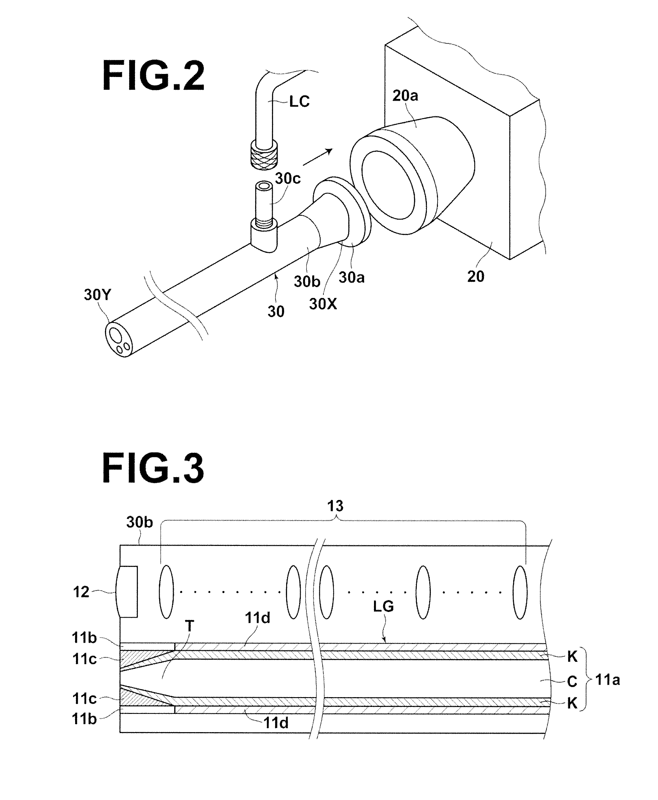
[0034]The endoscopic light guide for guiding illumination light to an observation target and the endoscope having the same according to the present invention includes, in particular, a radiation mode inducing means for causing the propagation mode light propagating through the optical fiber to make side face radiation in the vicinity of an output facet of the optical fiber through which the propagation mode light exits, thereby converting the propagation mode light to radiation mode light such that the radiation mode light can be utilized as the illumination light. This allows laser light to be extracted also from a portion of the optical fiber other than the output facet, thereby allowing a secondary light source having a large emitting area to be formed even with a thin optical fiber. This may lower the laser safety standard class for the endoscopic light guide and endoscope having the same even if a thin optical fiber is used.

Problems solved by technology

Generally, laser light emitted from a laser light source may sometimes be harmful to human body due to high power density even if it is a small amount of emission.
In this case, direct use of the optical fiber reduced in the diameter is dangerous from the view point of laser safety standard.
The method described in Japanese Unexamined Patent Publication No. 2005-328921, however, poses a problem that the extension range of emitting area is limited, although it may increase the emitting area to a certain extent.
In the mean time, the distance between the output facet of the optical fiber (primary light source) and the diffuser plate cannot be set arbitrarily due to the demand for reduced endoscopic light guide.
Consequently, enlargement of emitting area of the secondary light source formed on the diffusion plate is inevitably limited.
In such a case, only a small portion of the diffusion plate is used and, as a result, the size of illumination area is also limited.

Method used


Image

  • Endoscopic light guide and endoscope having the same
  • Endoscopic light guide and endoscope having the same
  • Endoscopic light guide and endoscope having the same

Examples


first embodiment

[0054][First Embodiment of Endoscopic Light Guide and Endoscope Having the Same]

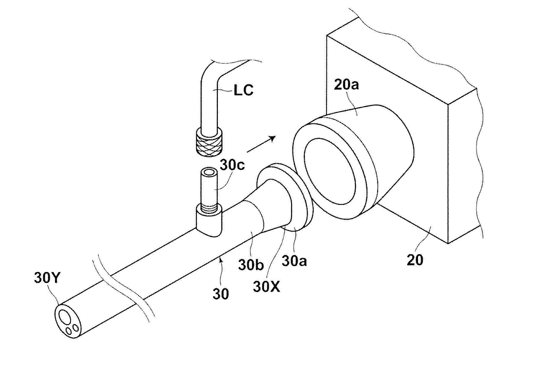
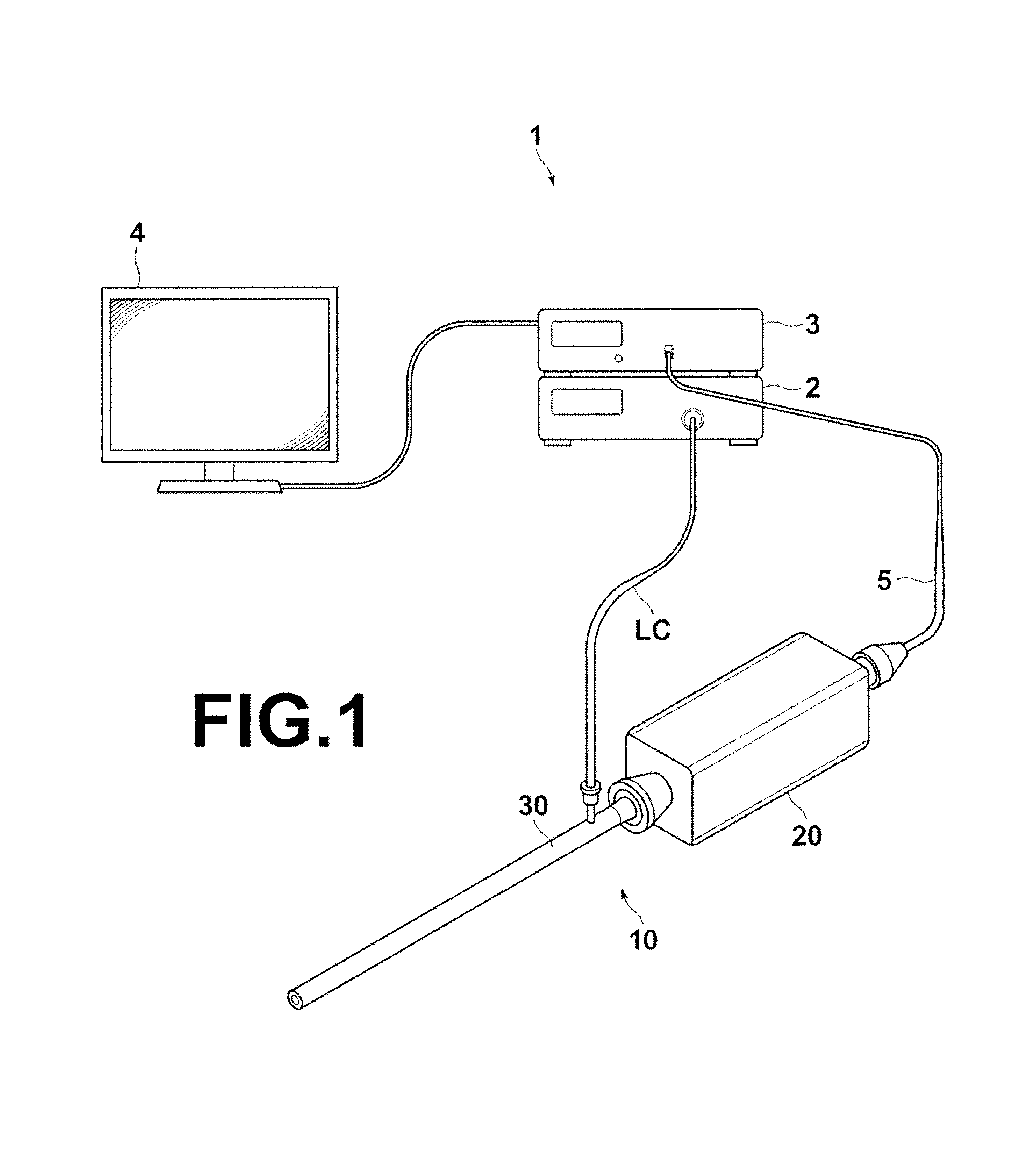
[0055]An endoscopic light guide or an endoscope having the same according to the first embodiment is used for an endoscope shown in FIG. 1. FIG. 1 is an external view of an endoscope system (rigid endoscope) which includes an endoscopic light guide (hereinafter, simply referred to as “light guide”) or an endoscope (rigid endoscope) having the endoscopic light guide according to the present embodiment.

(Rigid Endoscope System)

[0056]As illustrated in FIG. 1, rigid endoscope system 1 of the present embodiment includes light source device 2 for emitting white illumination light and / or excitation light, rigid endoscope 10 for guiding and illuminating the illumination light and / or excitation light emitted from light source device 2 to an observation area and capturing a visible image based on reflection light reflected, by illumination of the white light, from the observation area and / or a fluorescence image ba...

second embodiment

[0124][Second Embodiment of Endoscopic Light Guide and Endoscope Having the Same]

[0125]An endoscopic light guide and an endoscope having the same according to a second embodiment will now be described. The endoscopic light guide and endoscope having the same according to the present embodiment have configurations substantially identical to those of the first embodiment. The second embodiment differs from the first embodiment in that the radiation mode inducing means is pressing member 64 for pressing the side face of an optical fiber in the vicinity of the output facet of the optical fiber to generate microbending. Therefore, components identical to those of the first embodiment will not be elaborated upon further here unless otherwise specifically required.

[0126]FIGS. 11A and 115 illustrate aspects in which a pressing member which is the radiation mode inducing means of the present embodiment is mounted on an optical fiber. FIG. 11A is a schematic view of the optical fiber as viewe...


PUM


Abstract

An endoscopic light guide for guiding illumination light to an observation target is equipped with: an optical fiber; and a radiation mode inducing means for causing propagation mode light propagating through the optical fiber to make side face radiation in the vicinity of an output facet of the optical fiber through which the propagation mode light exits, thereby converting the propagation mode light to radiation mode light such that the radiation mode light can be utilized as the illumination light.

Description

BACKGROUND OF THE INVENTION[0001]1. Field of the Invention[0002]The present invention relates an endoscopic light guide to be inserted into a body cavity to guide and illuminate illumination light on an observation target. The invention also relates to an endoscope having the same.[0003]2. Description of the Related Art[0004]Endoscope systems for observing tissues of body cavities have been widely known and an endoscope system that obtains a visual image by illuminating, for example, white light on an observation target in a body cavity and imaging the observation target, and displays the visual image on a monitor screen has been widely put into practical use.[0005]Generally, the endoscope system described above uses an endoscopic light guide for guiding white light from a lamp light source to a body cavity as illumination light. Further, in order to realize more functional illumination (e.g., highlighting an affected area by the illumination of a specific wavelength) and for the sa...

Claims


Application Information

Patent Timeline
IPC IPC(8): A61B1/06
CPCA61B1/00105A61B1/0638A61B1/0017A61B1/07
Inventor KASAMATSU, TADASHIYOSHIDA, KOJI
Owner FUJIFILM CORP
Learn More