Ultrasonic transducer

Active Publication Date: 2013-01-24
CHONGQING HAIFU MEDICAL TECH CO LTD
View PDF3 Cites 44 Cited by
  • Summary
  • Abstract
  • Description
  • Claims
  • Application Information

AI Technical Summary

Benefits of technology

[0036]The ultrasonic transducer in the present invention well solves the problems in the ultrasonic treatment to deep tissue diseases of a human body and intracranial ultrasonic treatment. Under the condition that the safety of a human body is guaranteed, enough ultrasonic energy can reach deep tissues of a human body, and thermal damage caused by the absorption of ultrasonic waves by bone tissues on the ultrasonic path is avoided. Therefore, the ultrasonic transducer in the present invention is particularly suitable for treating deep tissues of a human body and intracranial nidus.
[0037]The ultrasonic transducer in the present invention not only can be provided with large ultrasonic emitting area and great focusing gain that render the energy of the ultrasonic focus enhanced dramatically, but also can be free from the influence of the work frequency of the ultrasonic source.
[0038]Compared with an existing ultrasonic tr

Problems solved by technology

However, the resonance enhancing points, which are not positioned at the spherical center, undergo limited times of resonance, so that the ultrasonic energy

Method used


Image

  • Ultrasonic transducer
  • Ultrasonic transducer
  • Ultrasonic transducer

Examples


embodiment 1

[0055]In this embodiment, the ultrasonic transducer comprises one ultrasonic emitting unit which has a function of reflecting ultrasound, and the ultrasonic emitting unit is a self-focusing ultrasonic transducer unit. The wavefront of the ultrasonic waves emitted by the ultrasonic emitting unit is a sphere surface with uniform radius, and the emitted ultrasonic waves are spherical waves. The ultrasonic emitting unit is configured to form a spherical resonant cavity, the internal cavity of which has a complete spherical shell shape so as to form a shell shaped spherical resonant cavity with a completely closed sound path. The focusing area of the shell shaped spherical resonant cavity is an area in which the spherical center of the spherical resonant cavity is located.

[0056]In the ultrasonic transducer of the present invention, the ultrasonic waves emitted by the ultrasonic emitting unit and the ultrasonic waves emitted or reflected by its opposite surface form a resonance-enhanced f...

embodiment 2

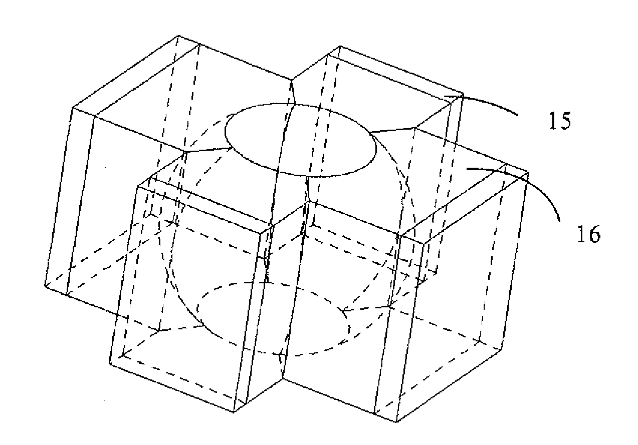
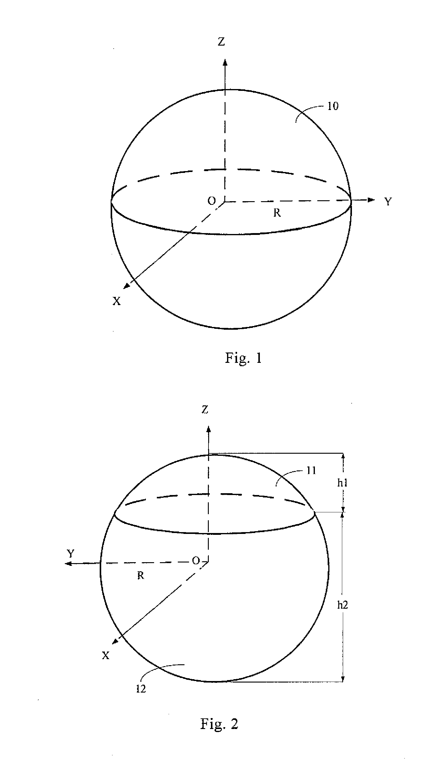
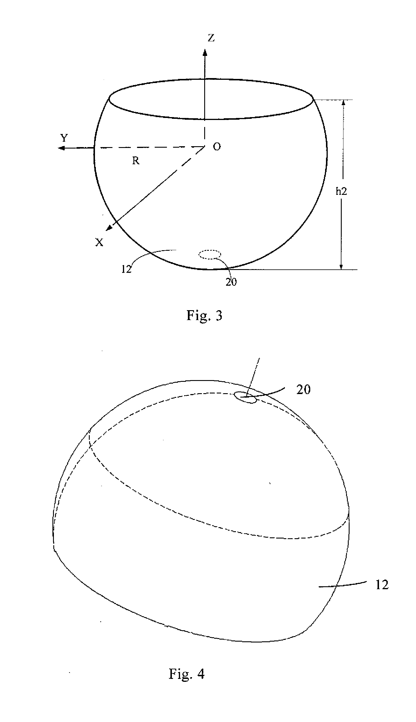
[0061]As shown in FIG. 2, in this embodiment, the internal cavity of the spherical resonant cavity formed by the ultrasonic transducer has a complete spherical shell shape, and the difference between Embodiment 2 and Embodiment 1 lies in that the spherical resonant cavity having a spherical shell shape is not formed by only one ultrasonic emitting unit. The internal cavity of the spherical resonant cavity having a spherical shell shape is formed by a truncated spherical cavity 12 (as shown in FIGS. 3 and 4) and a crown shaped spherical cavity 11 together. The bottom surface of the truncated spherical cavity 12 is fitted with and connected to the bottom surface of the crown shaped spherical cavity 11, and the connection between the truncated spherical cavity 12 and the crown shaped spherical cavity 11 is removable.

[0062]Wherein, the height h1 of the crown shaped spherical cavity 11 is smaller than the spherical radius R, and the height h2 of the truncated spherical cavity 12 is large...

embodiment 3

[0068]As shown in FIGS. 5, 6 and 7, in this embodiment, the internal cavity of the spherical resonant cavity formed by the ultrasonic transducer has a cross-sectional spherical shell shape with a spherical center therein, and the internal cavity is configured as a regular frustum shaped spherical cavity 13.

[0069]In this embodiment, the upper bottom surface S1 and the lower bottom surface S2 of the frustum shaped spherical cavity 13 are parallel to each other, and the distance between the upper bottom surface S1 and the spherical center O is equal to the distance between the lower bottom surface S2 and the spherical center O.

[0070]In this embodiment, the frustum shaped spherical cavity 13 can be formed from one ultrasonic emitting unit 1 (as shown in FIG. 5), or a plurality of ultrasonic emitting units 1 arranged in a single layer (as shown in FIG. 6), or a plurality of ultrasonic emitting units 1 arranged in multiple layers (as shown in FIG. 7). The one or the plurality of ultrasoni...


PUM


Abstract

An ultrasonic transducer is disclosed, which includes one or a plurality of ultrasonic emitting units. Wavefronts of the ultrasonic waves emitted by the one or the plurality of ultrasonic emitting units are sphere surfaces with uniform radius, and the one or the plurality of ultrasonic emitting units can reflect ultrasound. The one ultrasonic emitting unit is configured to form a spherical resonant cavity, or the plurality of ultrasonic emitting units are configured to form a spherical resonant cavity collectively. An internal cavity of the spherical resonant cavity has a spherical shell shape or a cross-sectional spherical shell shape with a spherical center therein. The ultrasonic waves emitted by the one or the plurality of ultrasonic emitting units are focused on an area in which the spherical center of the spherical resonant cavity is located. The ultrasonic transducer not only can be provided with a large ultrasonic emitting area and a great focusing gain that render the energy of the ultrasonic focus enhanced dramatically, but also can be free from the influence of work frequency of an ultrasonic source.

Description

TECHNICAL FIELD OF THE INVENTION[0001]The present invention belongs to the field of ultrasonic therapy technology, and particularly relates to an ultrasonic transducer.BACKGROUND OF THE INVENTION[0002]When ultrasound is used to treat diseases, owing to the great loss of ultrasonic energy on the transmission path, the ultrasonic intensity focused at a nidus is too low to achieve required clinical therapeutic effect. Therefore, for an ultrasonic treatment apparatus, the tough technical difficulties required to be solved currently are how to reduce severe attenuation of ultrasound on transmission paths as much as possible and how to enhance ultrasonic intensity at treated parts.[0003]In the prior art, a manner for solving the above technical problem is usually obtained by the design of an ultrasonic transducer. For an existing ultrasonic transducer, the size and intensity of the ultrasonic energy focusing area are usually relevant to the emitting area and work frequency of the ultrason...

Claims


Application Information

Patent Timeline
IPC IPC(8): A61N7/00
CPCA61B8/4455A61N7/02A61N2007/006B06B1/0637A61N2007/0078G10K11/32A61N2007/0069A61B8/00A61N7/00G01N29/24
Inventor WANG, ZHIBIAOWANG, HUAZENG, DEPINGZHAO, CHUNLIANGYE, FANGWEILI, SANYONGXU, GUIHUAGONG, XIAOBO
Owner CHONGQING HAIFU MEDICAL TECH CO LTD
Why Eureka
Try Eureka