Method of laser-welding and method of manufacturing battery including the same

a laser beam and battery technology, applied in sustainable manufacturing/processing, cell components, forging/pressing/hammering apparatus, etc., can solve the problems of difficult to obtain enough heat input, low output of laser machining apparatus using green laser, and inability to use laser welding to such members

Inactive Publication Date: 2012-03-08
TOYOTA JIDOSHA KK
View PDF101 Cites 39 Cited by
  • Summary
  • Abstract
  • Description
  • Claims
  • Application Information

AI Technical Summary

Benefits of technology

[0022]According to the embodiment of the present invention, the even welding for the members of high laser reflectance on the surface thereof is achieved.

Problems solved by technology

When laser welding the member with high laser reflectivity on the surface such as the copper member, most of the laser light reflects on the surface and it is difficult to obtain enough heat input.
Now, the laser welding to such member is not put to practical use.
Unfortunately, the laser machining apparatus using the green laser generally has low output, and hence the apparatus is used only for welding or machining of the thin member.
However, as mentioned above, if the normal laser machining apparatus is used, the enough heat input will not be obtained because the copper members reflect the laser beam or the laser output is low, and thereby, it is hard to provide enough welding depth.
Unfortunately, spatter and soot may occur or the welding point may be penetrated, whereby there is a problem with the weldability.
Furthermore, the laser machining apparatus with high laser output gives heat input to the surrounding members more than necessary, so that the members disposed around the welding point may cause thermal failure.
The roughening method of JP 2003-263977 A is applicable to roughen broadly, but that is hardly applicable to roughen the minute point evenly that has the shape variation such as step surface, so that the variation in the surface condition easily appears.
Moreover, the roughening methods need masking during the roughening process or cleaning after roughening, and the process may be complex so that it is troublesome to use in the production line.
So, the heat input during the laser welding becomes unstable and the welding failure easily happens.
Thus, the conventional laser welding method may fail to weld evenly the members of high laser reflectance on the surface.

Method used


Image

  • Method of laser-welding and method of manufacturing battery including the same
  • Method of laser-welding and method of manufacturing battery including the same
  • Method of laser-welding and method of manufacturing battery including the same

Examples


Embodiment Construction

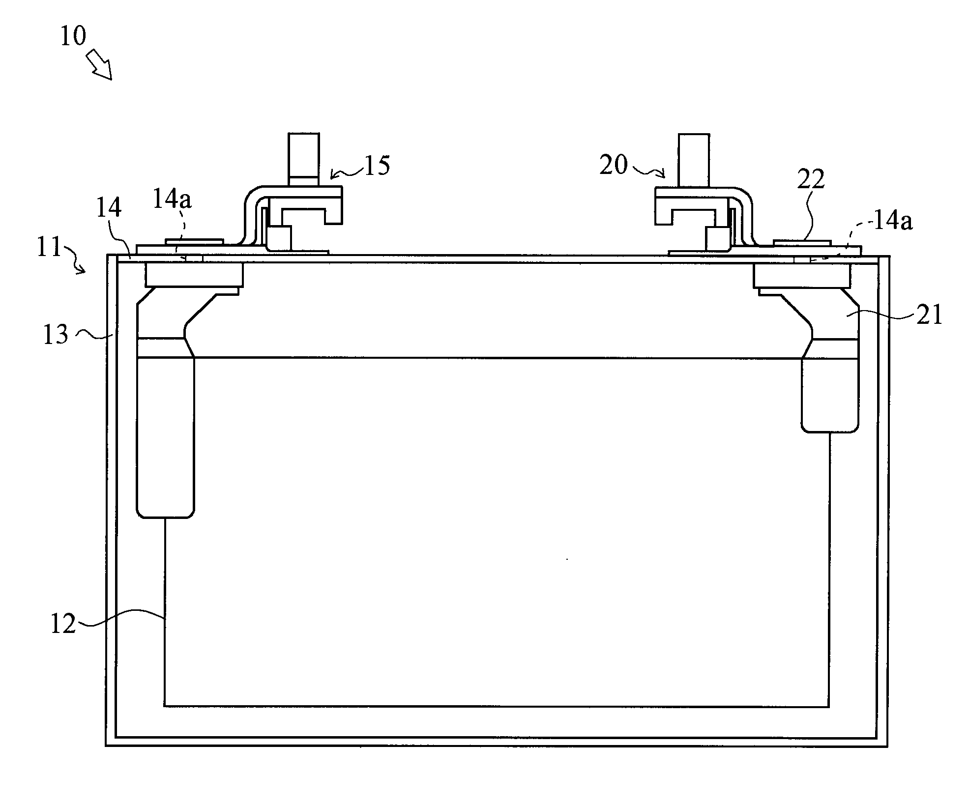
[0036]Referring to drawings, a laser welding step S1 as an embodiment of the present invention is described. In the laser welding step S1, a negative electrode terminal 20 and a negative electrode lead 21 composing the negative electrode of a battery 10 is welded by using laser beam.

[0037]Hereinafter, the structure of the battery 10 to be welded in the laser welding step S1 is explained.

[0038]The battery 10 is a lithium ion secondary battery, and as shown in FIG. 1, includes a casing 11 housing an electric power generating element 12. The casing 11 has a box 13 and a lid 14 covering the opening of the box 13. The lid 14 is formed with two holes 14a through which a positive electrode terminal 15 and the negative electrode terminal 20 are projected outward.

[0039]The negative electrode terminal 20 is an outer electrode terminal made of copper, and electrically connected to the element 12 via the negative electrode lead 21.

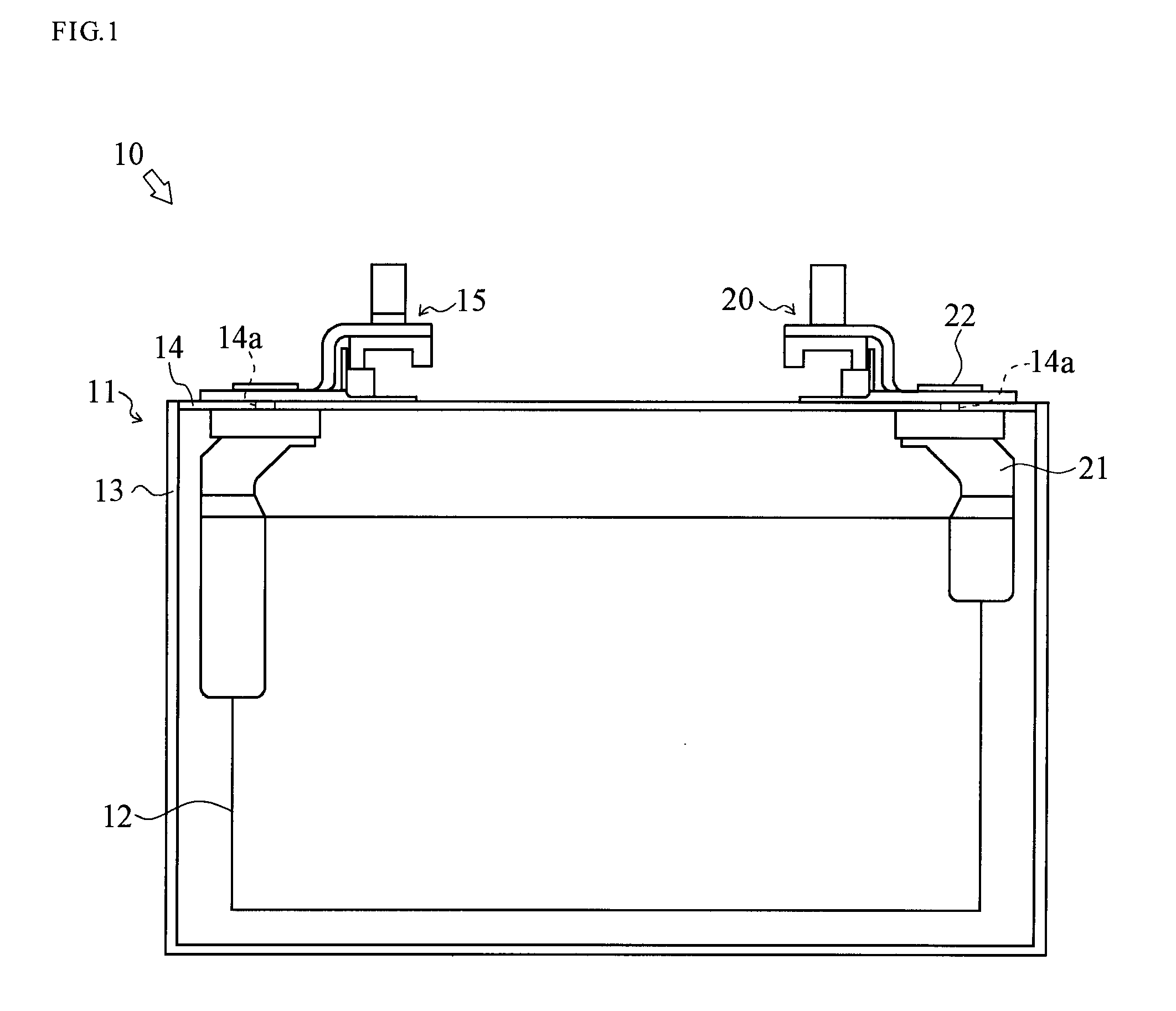
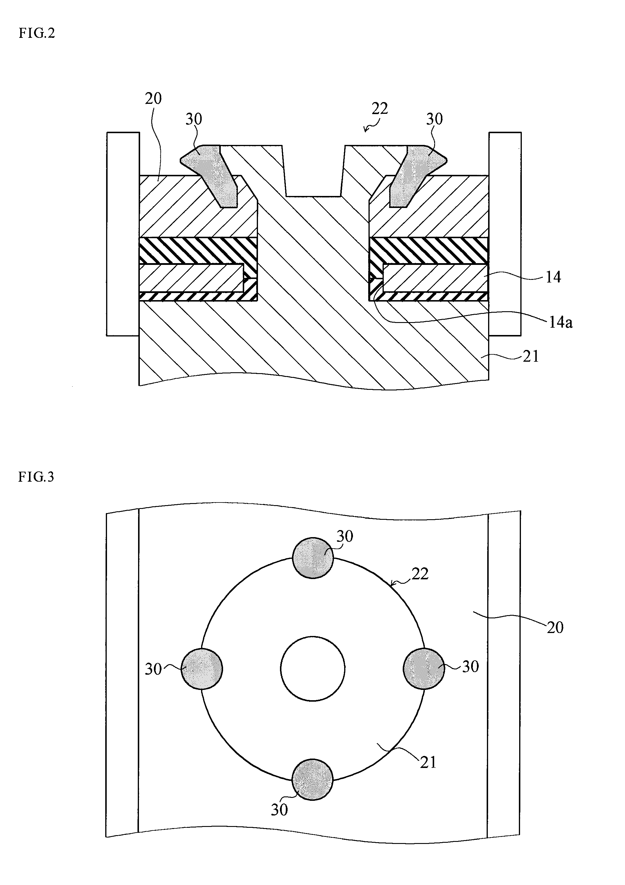
[0040]In detail, as depicted in FIGS. 2 and 3, the negative elec...


PUM

PropertyMeasurementUnit
depthaaaaaaaaaa
reflectanceaaaaaaaaaa
reflectivityaaaaaaaaaa

Abstract

Provided is a method of laser-welding that can achieve uniform welding of a member with large laser reflectance on a surface thereof A laser welding step (S1) includes a surface roughening step (S11) in which a first laser processing device irradiates laser light to a surface (each welding portion (31)) of a welding section (30, 30, 30, 30) between a negative electrode terminal (20) (a first member) and a negative electrode lead (21) (a second member) and carries out roughening, thereby forming a laser marker (32) on the surface; and a welding step (S12) in which a second laser processing device irradiates laser light to each welding portion (31) roughened in the surface roughening step (S11) and melts each welding portion (31), thereby carrying out the laser-welding of the negative electrode terminal (20) to the negative electrode lead (21).

Description

TECHNICAL FIELD [0001]The present invention relates to a method of welding using laser beam and a method of manufacturing a battery including the same, especially to a technique of laser welding a member, such as a copper member, having high laser reflectance on the surface thereofBACKGROUND ART [0002]There is a technique of bonding two metal members by using the laser welding, and that is broadly used in the industrial field.[0003]The laser welding using YAG laser beam is easy to be used under air atmosphere, and therefore it is really advantageous in the respect of costs and control, compared to other welding technique, e.g. the electron beam welding (EBW) which is performed under vacuum atmosphere. The laser welding using YAG laser tends to be applied to the mass production line.[0004]When laser welding the member with high laser reflectivity on the surface such as the copper member, most of the laser light reflects on the surface and it is difficult to obtain enough heat input. ...

Claims


Application Information

Patent Timeline
Patent Type & Authority Applications(United States)
IPC IPC(8): B23K26/00B23K26/14B23K26/21H01M50/528H01M50/536H01M50/55H01M50/553H01M50/562H01M50/566
CPCB21K25/00B23K26/0078B23K26/123H01M2/26B23K26/421H01M10/0525B23K33/00B23K26/28B23K26/32H01M2/30B23K26/60B23K26/3584Y02E60/10Y02P70/50H01M50/553H01M50/55H01M50/566H01M50/536H01M50/562B23K26/21B23K26/12H01M10/04B23K2101/38
Inventor MIYAKE, HIDEAKIOSHIMA, TAKAHIRO
Owner TOYOTA JIDOSHA KK
Why Eureka
Try Eureka