Exposure apparatus, movable body apparatus, flat-panel display manufacturing method, and device manufacturing method

a technology of movable body and exposure apparatus, which is applied in the direction of photomechanical apparatus, instruments, printing, etc., can solve the problems of decreased workability, increased cost, and increased surface plate size, and achieve high precision without affecting drive performance

Active Publication Date: 2012-03-08
NIKON CORP
View PDF1 Cites 128 Cited by
  • Summary
  • Abstract
  • Description
  • Claims
  • Application Information

AI Technical Summary

Benefits of technology

[0020]According to this apparatus, because the drive device utilizes the force in the first predetermined direction acting between the first mover and the first stator and the force in the second predetermined direction acting between the second mover and the second stator at the time when the movable body is driven as a levitation force of the movable body, the load including the self-weight of the movable body applied to the base is reduced, and the movable body can be driven with high precision without hindering drive performance.

Problems solved by technology

However, in recent years, substrates subject to exposure of exposure apparatuses tend to increase in size, and with it, the size of surface plates tend to increase, which may decrease transportability of the exposure apparatus, workability at the time of assembly and the like, in addition to an increase in cost.
Therefore, the weight cancellation device had to be large (tall), and a large drive force was necessary to drive the weight cancellation device along the horizontal plane.
Further, additional problems such as an increase in size of the substrate stage device, generation of frictional heat in the guide device and generation of Joule's heat in the linear motor, mechanical damage by adsorbates will become evident.

Method used


Image

  • Exposure apparatus, movable body apparatus, flat-panel display manufacturing method, and device manufacturing method
  • Exposure apparatus, movable body apparatus, flat-panel display manufacturing method, and device manufacturing method
  • Exposure apparatus, movable body apparatus, flat-panel display manufacturing method, and device manufacturing method

Examples


first embodiment

[0054]A first embodiment will be described below, with reference to FIGS. 1 to 7.

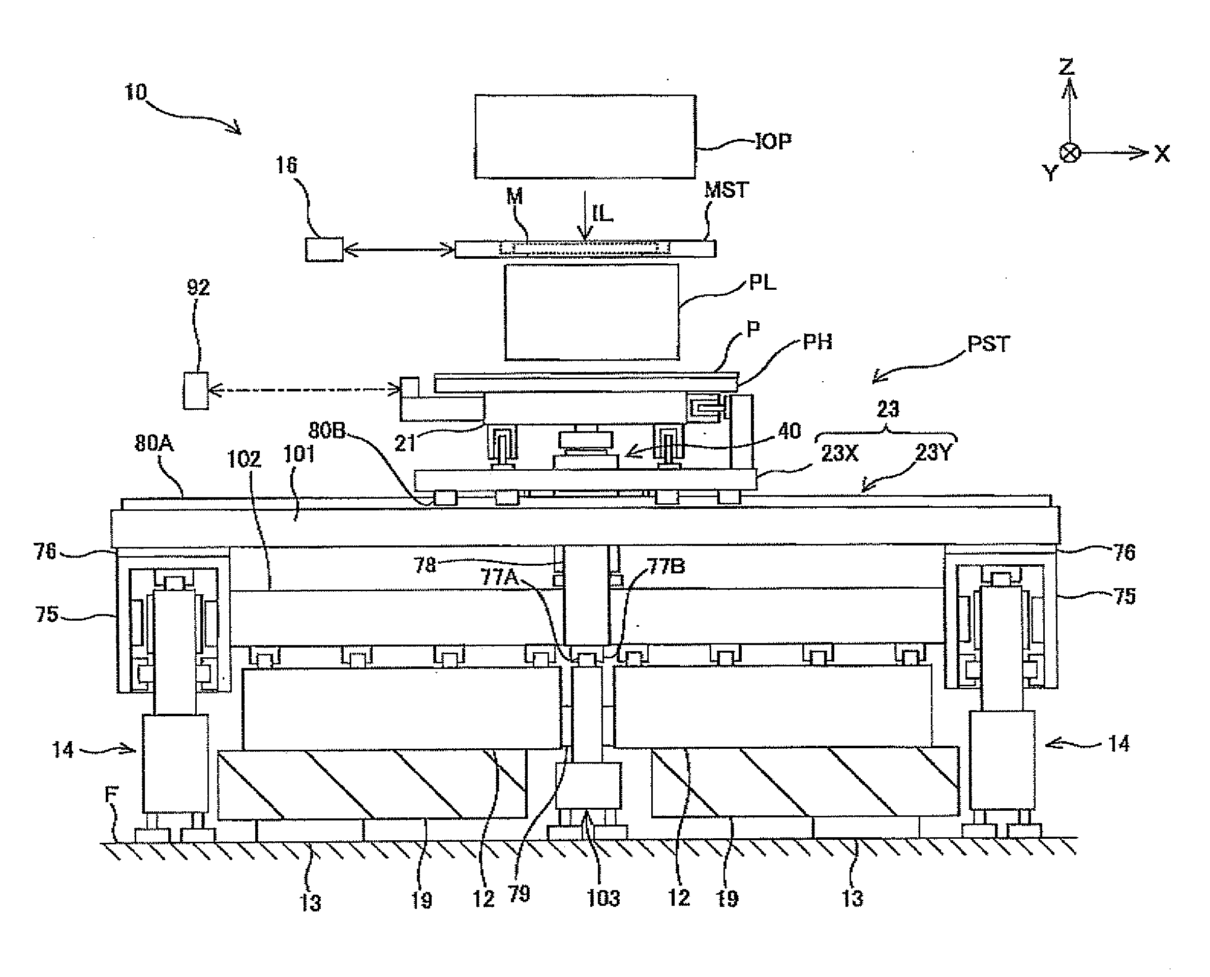
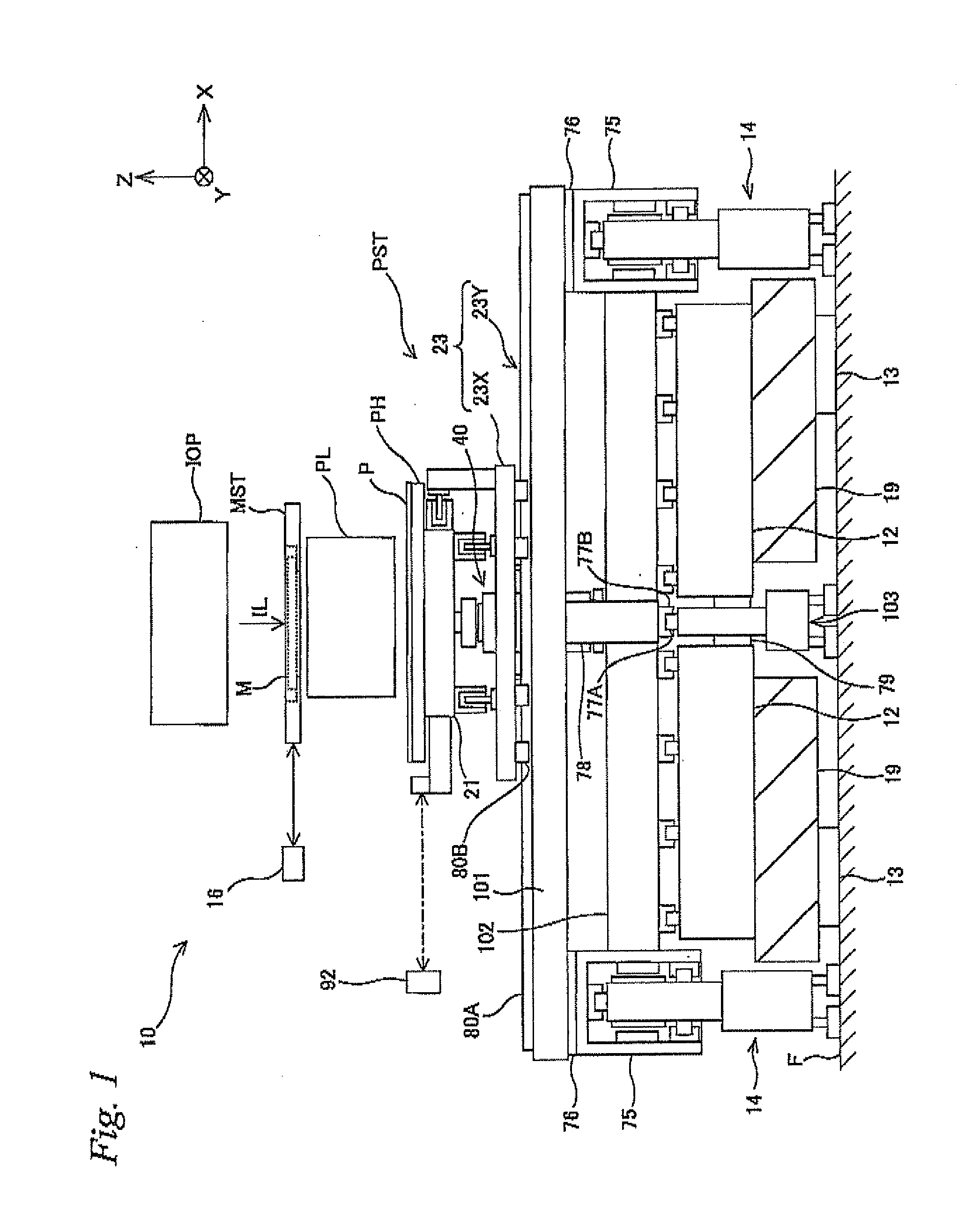
[0055]FIG. 1 schematically shows a configuration of an exposure apparatus 10 related to the first embodiment. Exposure apparatus 10 is a projection exposure apparatus by a step-and-scan method, or a so-called scanner in which a rectangular glass substrate P (hereinafter, simply referred to as a substrate F) that is used in a liquid crystal display device (flat panel display) serves as an exposure subject.

[0056]As shown in FIG. 1, exposure apparatus 10 is equipped with an illumination system IOP, a mask stage MST holding a mask M, a projection optical system PL, a pair of substrate stage mountings 19, a substrate stage PST holding a substrate P movable along a horizontal plane, and a control system and the like thereof. In the description below, the explanation is given assuming that a direction within a horizontal plane in which mask M and substrate P are scanned relative to projection optical system PL...

second embodiment

[0120]Next, a second embodiment of the present invention will be described, with reference to FIGS. 8 to 13. Herein, the same or similar reference signs are used for the components that are the same as or similar to those in the first embodiment described previously, and the description thereabout is simplified or omitted.

[0121]FIG. 8 schematically shows a configuration of an exposure apparatus 110 related to the second embodiment. Exposure apparatus 110 is a projection exposure apparatus by a step-and-scan method, or a so-called scanner in which a substrate P that is used in a liquid crystal display device (flat panel display) serves as an exposure subject.

[0122]FIG. 9 shows a planar view of a substrate stage device PSTa which exposure apparatus 110 of FIG. 8 has, and FIG. 10 shows a sectional view of line D-D in FIG. 9. Further, FIG. 11 shows a planar view (a sectional view of line E-E in FIG. 10) of the substrate stage device except for the fine movement stage, and FIG. 12 shows ...

third embodiment

[0139]Next, a third embodiment will be described, with reference to FIGS. 14 to 16. Because substrate stage PSTb related to the third embodiment has a configuration that is almost the same as substrate stage PSTa (refer to FIG. 9 and the like) of the second embodiment described above except for the point that the driving method of X guide 102 is different, the same or similar reference numerals will be used for the same or similar sections as in the second embodiment, and a description thereabout will be simplified or omitted.

[0140]While Y carriage 75 was fixed to both side surfaces of X beam 101 in the second embodiment described above, in the third embodiment, Y carriage 75 is fixed to the lower surface of X beam 101 similar to exposure apparatus 10 previously described, as shown in FIG. 15. Therefore, the height of base frame 14 (the same reference code is used for the sake of convenience) is lower when compared with the second embodiment. This allows substrate stage PSTb to be c...


PUM

PropertyMeasurementUnit
wavelengthaaaaaaaaaa

Abstract

In a substrate stage, when a Y coarse movement stage moves in the Y-axis direction, an X coarse movement stage, a weight cancellation device, and an X guide move integrally in the Y-axis direction with the Y coarse movement stage, and when the X coarse movement stage moves in the X-axis direction on the Y coarse movement stage, the weight cancellation device moves on the X guide in the X-axis direction integrally with the X coarse movement stage. Because the X guide is provided extending in the X-axis direction while covering the movement range of the weight cancellation device in the X-axis direction, the weight cancellation device is constantly supported by the X guide, regardless of its position. Accordingly, a substrate can be guided along the XY plane with good accuracy, even if a member (for example, a surface plate and the like) that has a guide surface large enough to cover the total movement range of the weight cancellation device is not provided.

Description

CROSS-REFERENCE TO RELATED APPLICATIONS[0001]This non-provisional application claims the benefit of Provisional Application No. 61 / 380,394 filed Sep. 7, 2010 and Provisional Application No. 61 / 380,397 filed Sep. 7, 2010, the disclosures of which are hereby incorporated herein by reference in their entirety.BACKGROUND OF THE INVENTION[0002]1. Field of the Invention[0003]The present invention relates to exposure apparatuses, movable body apparatuses, flat-panel display manufacturing methods, and device manufacturing methods, and more particularly, to an exposure apparatus used in a lithography process when semiconductor devices, liquid crystal display devices and the like are produced, a movable body apparatus that is suitable as a device which moves holding an object subject to exposure of the exposure apparatus, a flat-panel display manufacturing method which uses the exposure apparatus, and a device manufacturing method which uses the exposure apparatus.[0004]2. Description of the ...

Claims


Application Information

Patent Timeline
Patent Type & Authority Applications(United States)
IPC IPC(8): G03B27/42G03F7/20
CPCG03F7/70716G03F7/70816G03F7/709H02K7/09F16C29/008H02K41/031H02K2201/18F16C39/04F16C39/06H02K16/00B65G49/065G03F7/70791B65G2249/04F16C32/0421H01L21/0274G03F7/70775
Inventor AOKI, YASUO
Owner NIKON CORP
Why Eureka
Try Eureka