Efficient Sculpting System

a sculpting system and efficient technology, applied in the field of efficient sculpting system, can solve the problems of inability to achieve the prior art of manually manipulating and robotically monitoring surgical drills, inability to achieve optimal drill rpm, so as to reduce the operational time and attendant fatigue of surgeons, the effect of reducing the operational cos

Inactive Publication Date: 2012-03-08
FARRELL JAMES DAVID
View PDF1 Cites 109 Cited by
  • Summary
  • Abstract
  • Description
  • Claims
  • Application Information

AI Technical Summary

Problems solved by technology

This technique requires, at a minimum, an active five degree of freedom system with servo controlled joint actuators, which presents an intrinsic safety issue since “runaway conditions” or unexpected motion are possible due to a hardware malfunction or a software programming error.
The implementation effort and maintenance support of an effective safe control to reduce the risk of injury to humans situated within the working envelope of a robot inherently incurs considerable engineering, manufacturing and liability insurance costs.
Consequently, the optimal drill RPM, which promotes higher surgical throughput and more responsive reaction to potential injurious region intrusion, cannot be achieved by the prior art of manually manipulated and robotically monitored surgical drills.
These predictive models for bone removal rates cannot leveraged in prior art to estimate accurate arrival times of drill burrs in surgical operations since burr contact forces are not measured.
For example, if it requires 80 ms (milliseconds) to stop the rotation of the drill then an optimal RPM cannot create a situation, in which the drill burr may possibly reach an injurious zone in less than 80 ms.
The prior art of surgical resection applications with a manually maneuvered drill achieve inefficient but reasonably safe throughput by commanding suboptimal RPM (revolutions per minute), which represents the highest rotational drill speed that can be stopped before the surgeon inadvertently injures a critical anatomical region with a rotating drill burr.
A position only sensing scheme has an associated excessive and unresponsive time lag and subsequently lower bandwidth RPM control.
With no force sensing capability, prior art controllers cannot distinguish drill motion that was caused by the surgeon intentionally stroking the bone or by the tool walking from the tangential contact forces of the rotating burr.

Method used


Image

  • Efficient Sculpting System
  • Efficient Sculpting System
  • Efficient Sculpting System

Examples


Embodiment Construction

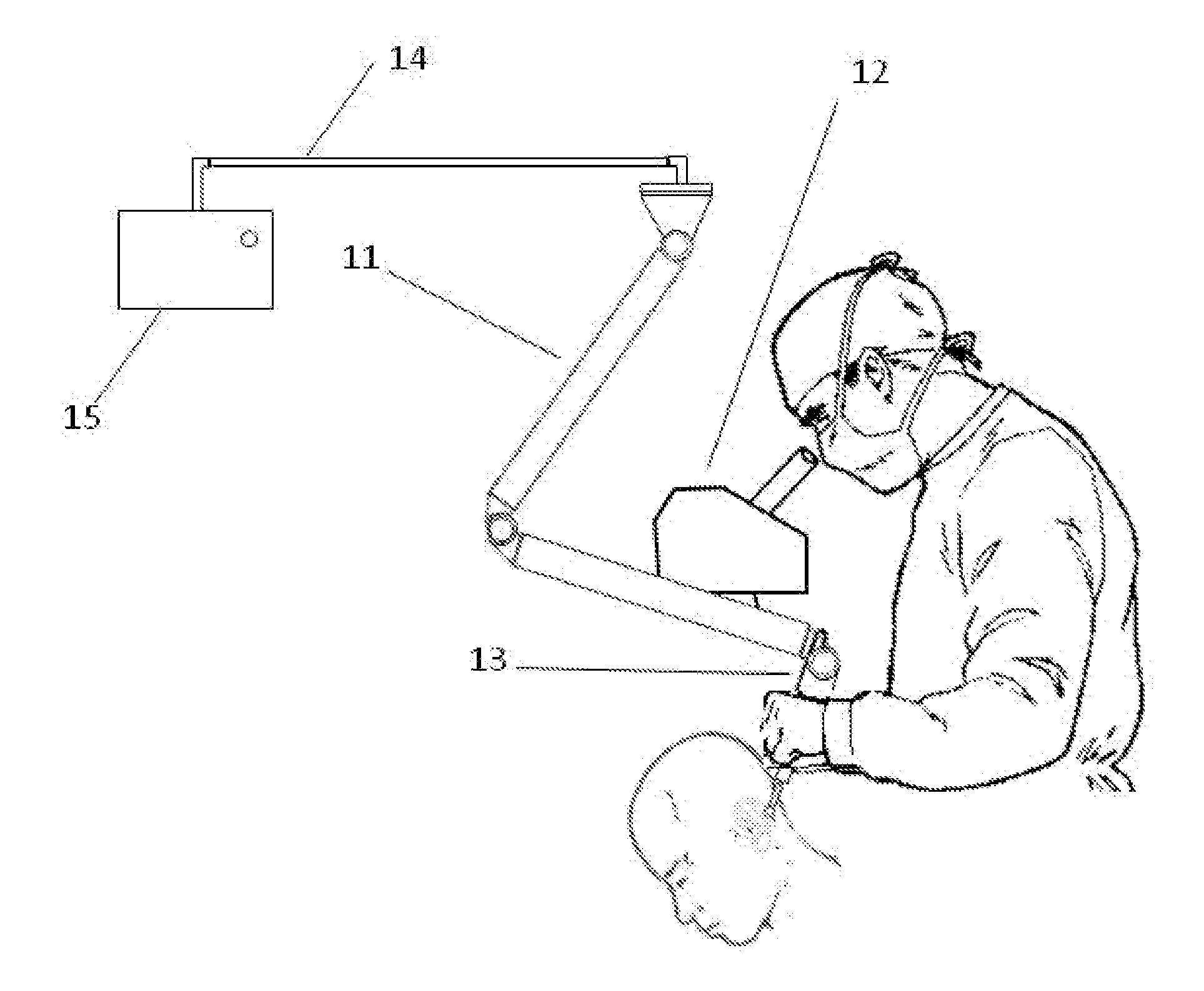
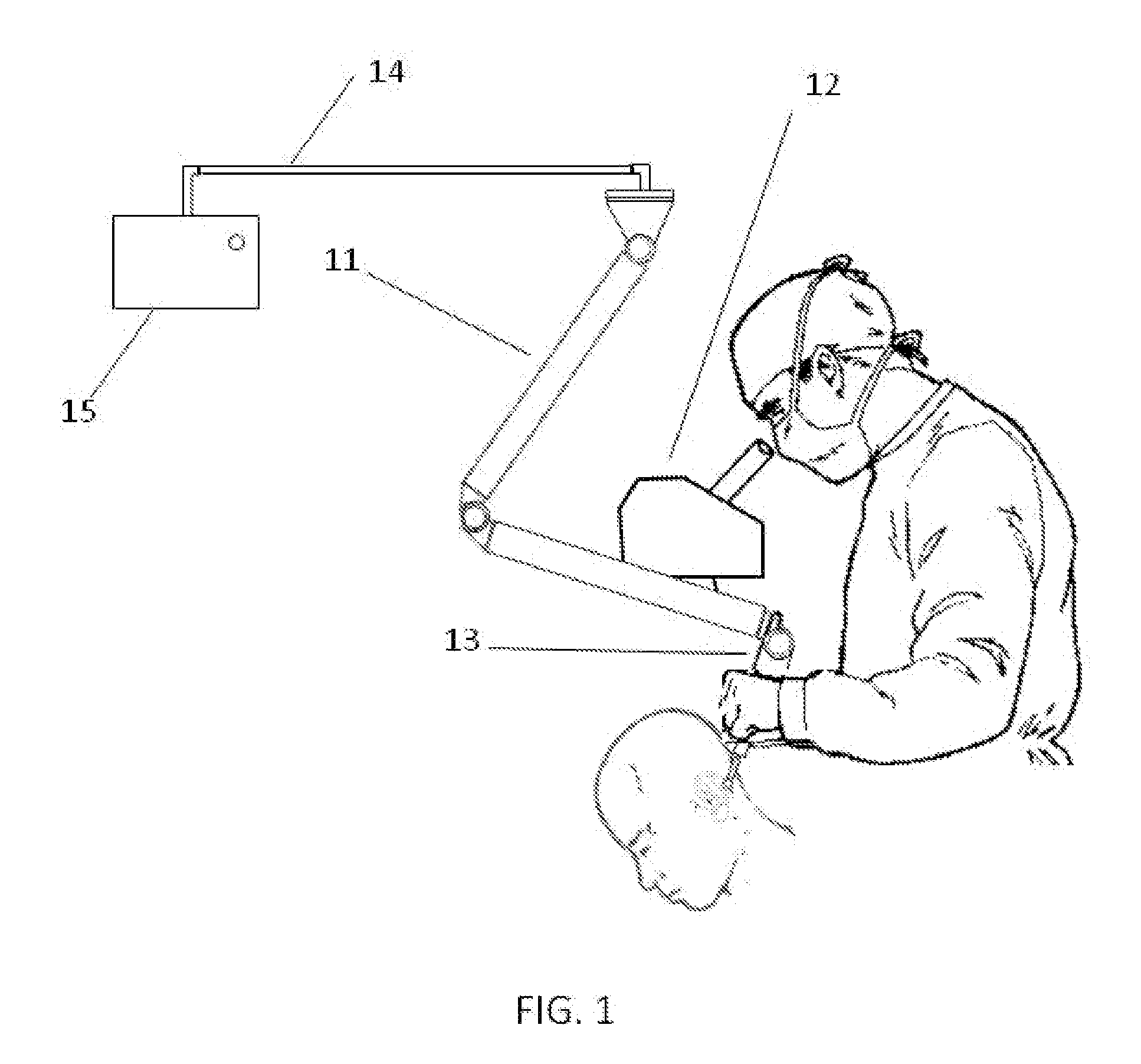
[0036]FIG. 1 illustrates an articulated coordinate measurement machine (ACCM) 11 as the tracking device in lieu of other candidates such as infrared optical trackers with three active infrared light emitting markers on the tool. The ACCM 11 consists of a configuration of seven joints with high resolution encoders, which permits the location and orientation of the drill burr to be tracked. The ACCM 11 affords the opportunity to instill high accuracy in the passive tracking system. Well established kinematic calibration techniques, which involve regression analysis and joint mapping techniques, permit volumetric measurement accuracies of 0.0005″. Thermal and gravity models may be employed to compensate for the thermal expansion and distortion and load deflection of the ACCM structure. However, an ACMM structure consisting of composite materials, which are extremely stiff and have very low thermal expansion coefficients, may avoid thermal and load deflection compensation since the stru...


PUM


Abstract

A system and method to optimize the material removal rate of a tool in a safe and geometrically precise manner, to facilitate the application of smooth contact forces and to sense tool contact forces for rapidly providing power regulation safeguards against tool inadvertently intruding into forbidden regions, for verifying and correlating physically extracted material against the virtual model, and for detecting and mitigating drill walking.

Description

CROSS-REFERENCE TO RELATED APPLICATIONS[0001]This application claims the benefit of provisional patent application Ser. No. 61 / 264,590 filed 2009 Nov. 25 by the present inventor.[0002]The following is a tabulation of some prior art that presently appears relevant,U.S. Patents[0003]Patent NumberKind CodeIssue DatePatentee6,757,582B22004 Jun. 29Brisson7,346,417B22008 Mar. 18LuthU.S. Patent Application Publications[0004]Patent NumberKind CodePublication DateApplicant079,898B22005 Mar. 18LabadieNon-Patent Literature Documents[0005]Morris D, Sewell C, Barbagli F, Blevins N, Girod S, Salisbury K. Visuohaptic Simulation of Bone Surgery for Training and Evaluation. IEEE Computer Graphics and Applications, Vol. 26, No. 4, November 2006, p 48-57.BACKGROUND OF THE INVENTION[0006]Robotic technology has been integrated successfully into the bone surgical process, particularly in operations that involve prosthetic implants for knee replacements. Robotic surgical assistance requires a virtual soli...

Claims


Application Information

Patent Timeline
Patent Type & Authority Applications(United States)
IPC IPC(8): A61B17/16
CPCA61B17/1624A61B17/1626A61B17/1628A61B17/1679A61B2019/505A61B19/26A61B2017/00084A61B2017/00199A61B2017/00787A61B17/1703A61B90/25A61B90/50A61B2034/105
Inventor FARRELL, JAMES DAVID
Owner FARRELL JAMES DAVID
Why Eureka
Try Eureka