High density, low jitter, synchronous USB expansion

a high density, synchronous usb technology, applied in the direction of synchronisation signal speed/phase control, instruments, generating/distributing signals, etc., can solve the problems of usb 2.0 specification lacked a mechanism for synchronising devices to any great precision, inter-device synchronization is not addressed, usb 2 lacked a jitter reduction effect, etc., to achieve the effect of reducing jitter in retransmission

Inactive Publication Date: 2012-03-08
CHRONOLOGIC PTY LTD
View PDF26 Cites 20 Cited by
  • Summary
  • Abstract
  • Description
  • Claims
  • Application Information

AI Technical Summary

Benefits of technology

[0069]The USB Hub re-clocking rate is preferably synchronised to be substantially an integer multiple of the bit rate of the USB data stream (in order to over-clock the sampling and retransmission of the USB data stream). In this way there is a constant phase relationship between the bit rate of the USB data stream and the plurality of clocks used to retransmit the USB data stream, to minimise jitter in retransmission of the USB data stream by the plurality of USB Hubs.

Problems solved by technology

However, USB was user focussed so the USB 2.0 specification lacked a mechanism for synchronising devices to any great precision.
This provides a degree of synchronization sufficient to read smart card information into a host PC but, as this approach is directed to a smart card reader, inter-device synchronization is not addressed.
All of the above systems work within the bounds of conventional USB 2.0 and as such are limited in several areas.
USB 2.0 is limited in range by the device response timeout.
In particular, the background art synchronisation schemes discussed above will not work with the new 5 Gb / s protocol (termed ‘SuperSpeed USB’) because it does away with the broadcast mechanism for SOF packets.
Very high speed communication systems consume large amounts of power owing to high bit rates.
This significantly affects any extension of the synchronisation schemes of, for example, U.S. patent application Ser. No. 12 / 279,328, whose method and apparatus for synchronising devices is based on a broadcast clock carrier signal that is delivered to each device on the bus, which is unsuitable in SuperSpeed USB.
A heavily burdened Hub function can therefore add significant non-deterministic delays in packet transmission through the system.
Unfortunately the Isochronous Timestamp packet can be delayed in propagation down the USB network.
USB 3.0 also does not provide a way of determining the propagation time of packets in SuperSpeed USB and hence no way of accurately knowing the phase relationship between time domains on different USB devices.
Phase differences of several hundred nanoseconds are expected to be a best case scenario with SuperSpeed USB making it impractical for instrumentation or other precision timing requirements.
This continual messaging consumes bandwidth and limits the accuracy of the possible synchronisation to several hundred nano-seconds in a point-to-point arrangement and substantially lower accuracy (typically micro-seconds) in a conventional switched subnet.

Method used


Image

  • High density, low jitter, synchronous USB expansion
  • High density, low jitter, synchronous USB expansion
  • High density, low jitter, synchronous USB expansion

Examples


Embodiment Construction

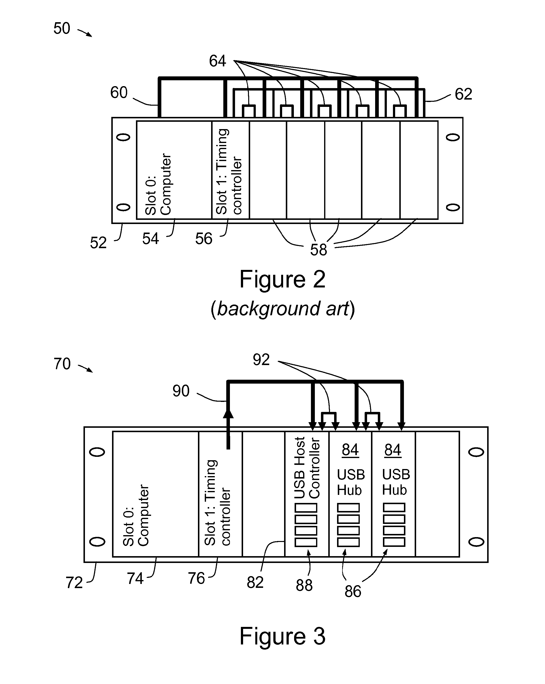
[0086]FIG. 2 is a schematic representation of the architecture of a PXI instrumentation chassis 50 according to the background art. The PXI chassis 52 contains a slot 54 for a computer (viz. slot 0 of chassis 52, which typically houses a rugged embedded PC), a timing controller slot 56 (viz. slot 1 of chassis 52), and a plurality of expansion slots 58. These components are connected by several busses 60, 62, 64 across the backplane (which also provides power to the modules as required).

[0087]Main communication is provided across the PCI bus 60. All data is transferred between the embedded computer (connected to slot 0) and attached timing controller (connected to slot 1) and plug-in modules 58 across PCI bus 60. Slot 1 may contain a special timing controller device that provides coordination of the different plug-in modules via delivery of clock and trigger event signals across the backplane's Star Trigger Bus 62. Finally a PXI Local Bus 64 is provided for sideband communication bet...


PUM


Abstract

A method of providing high density expansion of a USB network, the method comprising: attaching a plurality of USB hubs to adjacent slots in a PXI instrumentation chassis; configuring one of the USB hubs as a primary USB Hub; connecting an upstream port of the primary USB Hub to a USB network; configuring a first downstream port of the primary USB Hub to communicate across a first PXI Local Bus to a first adjacent USB Hub of the USB Hubs other than the primary USB Hub, the first adjacent USB Hub being adjacent to the primary USB Hub; configuring a plurality of other downstream ports of the primary USB Hub to provide expansion of the primary USB Hub; connecting an upstream port of the first adjacent USB Hub to the first PXI Local Bus, wherein the first PXI Local Bus is in the direction of the primary USB Hub; configuring a first downstream port of the first adjacent USB Hub to communicate across a second PXI Local Bus to a second adjacent USB Hub of the USB Hubs other than the primary USB Hub, the second adjacent USB Hub being adjacent to the first adjacent USB Hub; configuring a plurality of other downstream ports of the first adjacent USB Hub to provide expansion of the first adjacent USB Hub; and configuring any other of the USB hubs and the first adjacent USB Hub in like manner.

Description

RELATED APPLICATION[0001]This application is based on and claims the benefit of the filing date of U.S. application Ser. No. 61 / 179904 filed 20 May 2009, the content of which as filed is incorporated herein by reference in its entirety.FIELD OF THE INVENTION[0002]The present invention relates to a method and apparatus for providing a synchronization and timing system, with connectivity based on revision three of the Universal Serial Bus (USB) architecture (or USB 3.0), of particular but by no means exclusive use in providing clocks, data acquisition and automation and control of test and measurement equipment, instrumentation interfaces and process control equipment, synchronized to an essentially arbitrary degree in either a local environment or in a distributed scheme.BACKGROUND OF THE INVENTION[0003]The USB specification up to and including revision 2.0 was intended to facilitate the interoperation of devices from different vendors in an open architecture. USB 2.0 data is encoded...

Claims


Application Information

Patent Timeline
Patent Type & Authority Applications(United States)
IPC IPC(8): G06F13/14
CPCG06F1/12G06F13/4022G06F2213/0042H04L7/04G06F13/4027H04L7/08G06F1/08G06F13/10G06F13/423G06F13/4282G06F11/3027G06F13/405
Inventor FOSTER, PETER GRAHAM
Owner CHRONOLOGIC PTY LTD
Why Eureka
Try Eureka