Iron

a technology of electric irons and irons, applied in the field of electric irons, can solve the problems of reducing affecting the efficiency of the system, and affecting and achieving the effect of reducing the cost of production and maintenance, and improving the efficiency of the system

Inactive Publication Date: 2012-03-15
MORPHY RICHARDS LTD +1
View PDF25 Cites 12 Cited by
  • Summary
  • Abstract
  • Description
  • Claims
  • Application Information

AI Technical Summary

Benefits of technology

[0008]Use of a high thermal conductivity material or substrate for the tubes facilitates a relatively low temperature for the heated ATO films, for example less than 200° C.
[0072]In other embodiments, there may be provided a semiconductor thin film heating element with no semiconductor thin film fuse, but with a mechanical fuse in series with the thin film heating element. In yet other embodiments there may be provided a mechanical fuse in series with a semiconductor thin film fuse on the direct power to the heating element to provide additional safety.

Problems solved by technology

This method produces a small and varying amount of steam and is really only suitable for small amounts of clothes.
The main disadvantage is that the steam can cool down in the pipe and the system is very inefficient and takes a long time to warm up.
However, current nichrome heating technology has a power density limitation, because if the heater becomes too hot, then it will oxidize or burn out.
Thus without making the iron much larger and having a dramatic impact on the sole plate temperature, the volume of steam generation is limited.
A further disadvantage of this method is that the steam has to be re-heated at the iron and this can impact on the sole plate temperature at higher flow rates initially when the iron is cold, until the iron is at the correct working temperature.
In particular, if a sole plate with poor thermal conductivity is used, then this will become a potentially large problem.

Method used


Image

  • Iron
  • Iron
  • Iron

Examples


Embodiment Construction

[0103]There will now be described by way of example a specific mode contemplated by the inventors. In the following description numerous specific details are set forth in order to provide a thorough understanding. It will be apparent however, to one skilled in the art, that the present invention may be practiced without limitation to these specific details. In other instances, well known methods and structures have not been described in detail so as not to unnecessarily obscure the description.

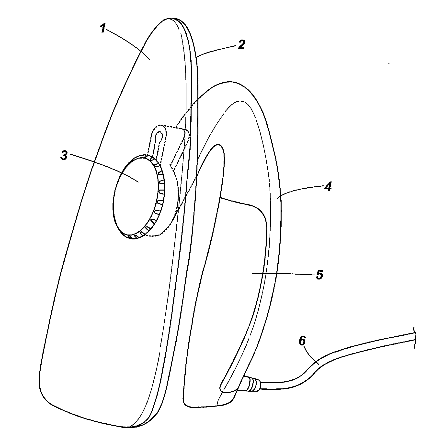
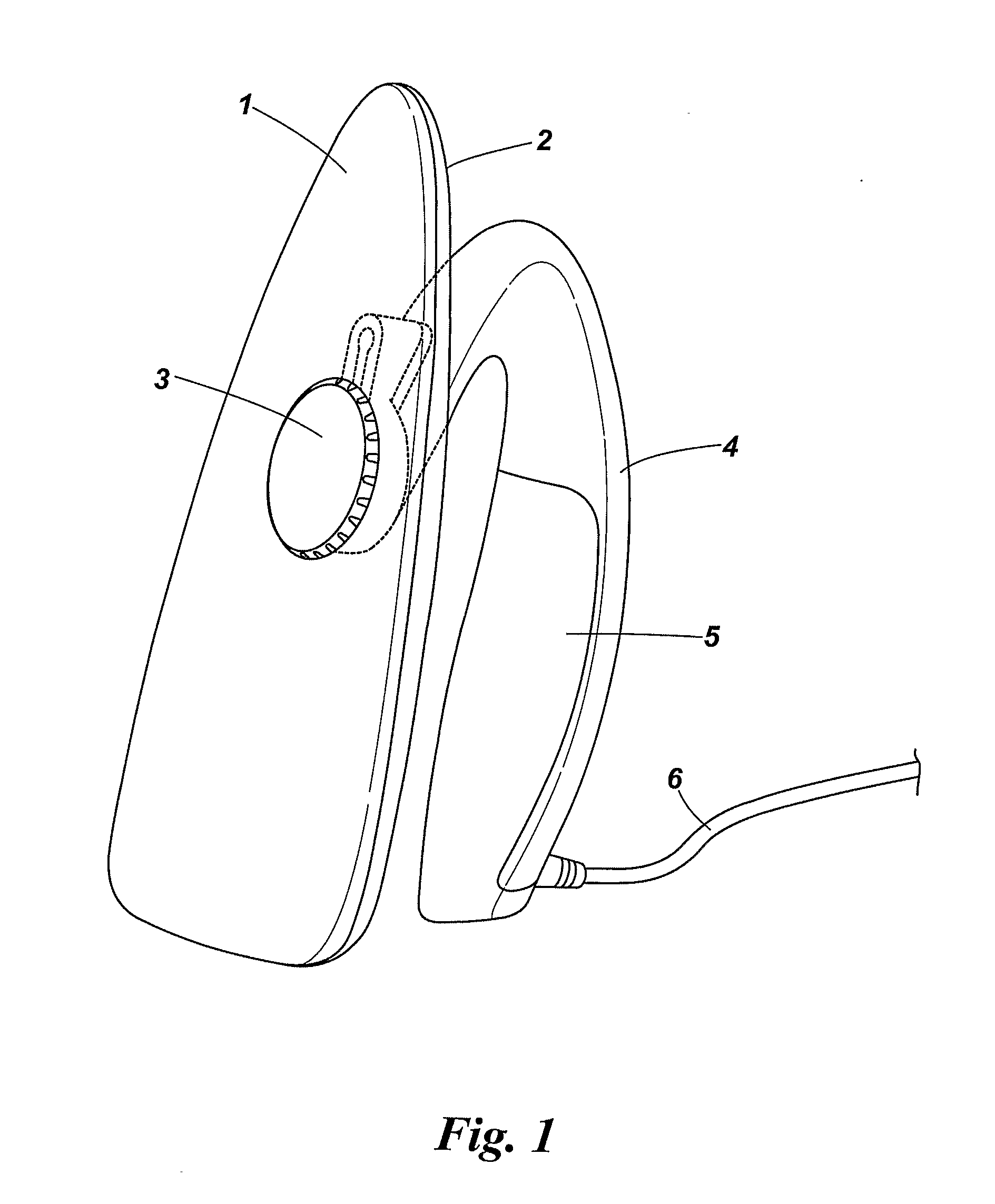
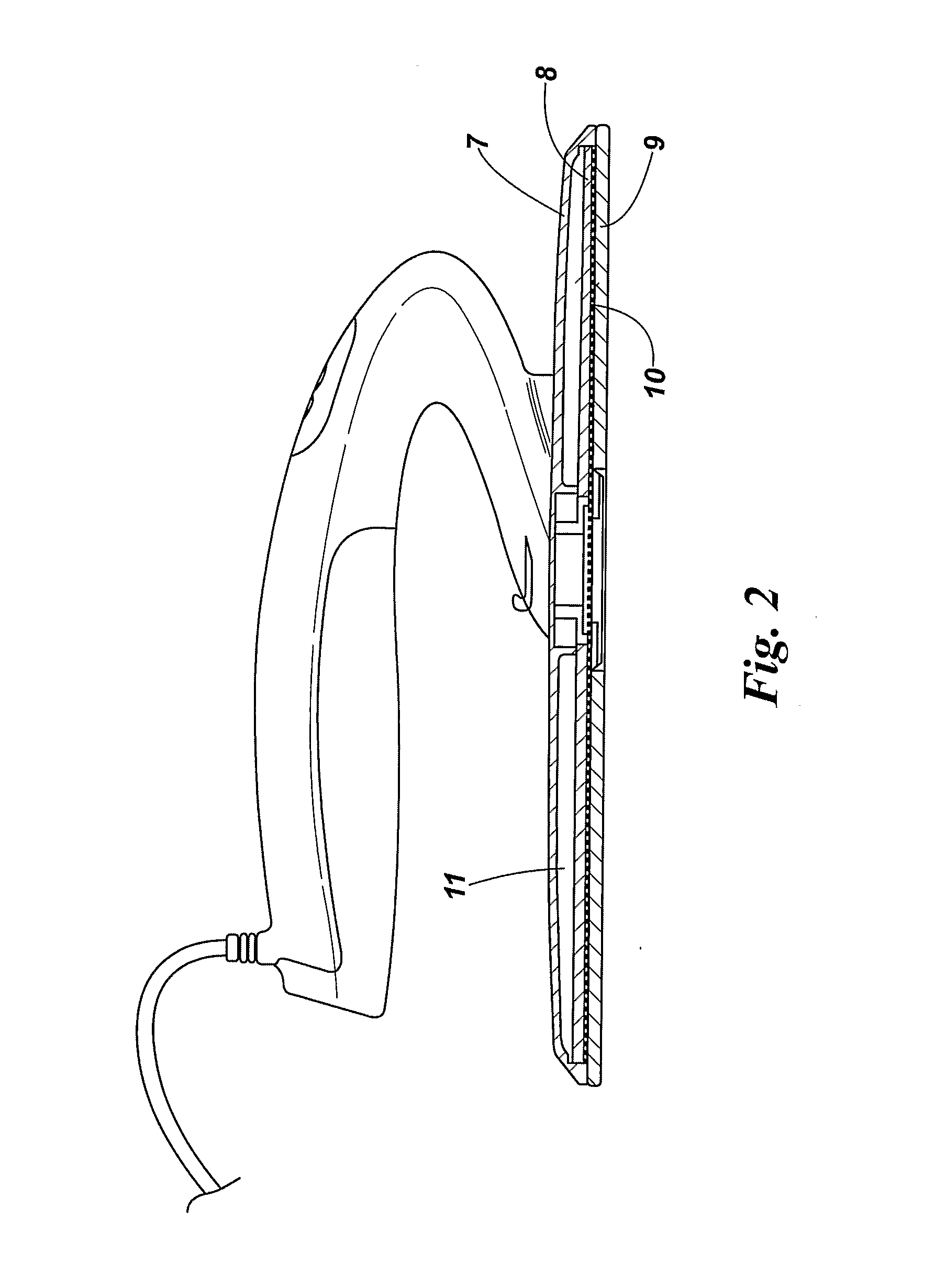
[0104]In specific embodiments disclosed herein, there is provided an iron having a glass or ceramic sole plate, which is heated directly by a thin film semi-conductor material, for example an antimony tin oxide coating, or an equivalent semi-conductor coating, for example doped indium tin oxide (ITO) or doped fluorine tin oxide (FTO).

[0105]In this specification, where the term antimony tin oxide is used, this encompasses materials including antimony oxide and tin oxide, and including materials...


PUM

PropertyMeasurementUnit
temperatureaaaaaaaaaa
band gapsaaaaaaaaaa
widthaaaaaaaaaa

Abstract

The invention relates to an electrical iron. An iron comprises a sole plate (1), of a glass or ceramic substrate bearing an electrical heating element. The electrical heating element comprises a transparent or translucent antimony tin oxide thin film which directly heats the glass or ceramic substrate.

Description

FIELD OF THE INVENTION[0001]The present invention relates to electrical irons.BACKGROUND TO THE INVENTION[0002]Domestic irons consists of a heated metal sole plate onto which water from a reservoir is dripped to generate steam, which is then emitted through holes in the sole plate. The clothes are then pressed by an action of heat and steam. This method produces a small and varying amount of steam and is really only suitable for small amounts of clothes.[0003]An improvement has been made through the introduction of separate water reservoir and steam generators. In this embodiment, a water tank and steam generator is separate from the iron, which also consists of a heated sole plate. The generated steam is then sent down a pipe to the iron, where a constant stream of steam is then released onto the clothes. This method has the advantage of a large water tank for heavy use and a constant flow of steam. The main disadvantage is that the steam can cool down in the pipe and the system is...

Claims


Application Information

Patent Timeline
Patent Type & Authority Applications(United States)
IPC IPC(8): D06F75/38D06F75/24D06F75/10
CPCD06F75/24D06F75/38D06F75/10D06F71/34D06F73/00F22B1/28
Inventor JAMES, MIKESELLORS, JAMIE MICHAELADKINS, GEORGE RALPHGREGORY, RICHARD
Owner MORPHY RICHARDS LTD
Why Eureka
Try Eureka